Bjt Equivalent Circuit Models
Found 8 free book(s)
Chapter 14 BJT Models - University of Washington
class.ece.uw.eduBJT Models Using the BJT Element Star-Hspice Manual, Release 1998.2 14-7 BJT Equivalent Circuits HSPICE uses four equivalent circuits in the analysis of BJTs: DC, transient, AC, and AC noise circuits. The components of these circuits form the basis for all element and model equations. Since these circuits represent the entire BJT in

BJT Equivalent Circuit Models - University of North ...
coefs.uncc.eduSection C3: BJT Equivalent Circuit Models OK, we’ve got the terminal currents defined in terms of our gain constants and each other. Now… we’ve got to come up with a model for the entire device that we can put in an electrical circuit for design and analysis! The large signal model introduced in section 4.2 of your text (and illustrated

ECE 255, MOSFET Small Signal Analysis - Purdue University
engineering.purdue.edu2 Small Signal Equivalent-Circuit Models By looking at the i-vcharacteristic curve of the MOSFET as shown in Table 5.1, it is seen for incremental v ds, the current i d does not change. This relationship can be modeled by a current source. Moreover, the gate of the MOSFET is essentially an open circuit at DC. Hence, the small-signal equivalent ...
Modeling and Simulation of Permanent Magnet Synchronous ...
www.irphouse.comIII Equivalent Circuit of Permanent Magnet Synchronous Motor Equivalent circuits of the motors are used for study and simulation of motors. From the d-q modeling of the motor using the stator voltage equations the equivalent circuit of the motor can be derived. Assuming rotor d axis flux from the permanent magnets

Lecture 20: Frequency Response: Miller Effect
inst.eecs.berkeley.eduMethod of Open Circuit Time Constants This is a technique to find the dominant pole of a circuit (only valid if there really is a dominant pole!) For each capacitor in the circuit you calculate an equivalent resistor “seen” by capacitor and form the time constant τ i =R i C i The dominant pole then is the sum of these time constants in the ...

Lecture 15: MOS Transistor models: Body effects, SPICE models
inst.eecs.berkeley.edusignal models: Chapter 6 zwe will then take a week on bipolar junction transistor (BJT): Chapter 7 zThen go on to design of transistor amplifiers: chapter 8 Department of EECS University of California, Berkeley EECS 105 Spring 2004, Lecture 15 Prof. J. S. Smith MOS operation zAn inversion mode MOS transistor operates by producing
MOSFET/IGBT DRIVERS THEORY AND APPLICATIONS - IXYS …
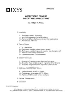
www.ixys.comPARASITIC BJT DRAIN DRAIN BODY DEPLETION LAYER INTERNAL BODY DIODE O V GS Actual Linearized gm = DRAIN CURRENT ID VGS(th) VGS ID ID VGS Fig. (2) Transfer characteristics of a power MOSFET 1.2 MOSFET MODELS AND CRITICAL PARAMETERS Fig. (1A) shows the internal cell structure of a DMOS MOSFET. As can be seen, the Gate to …
Bipolar Transistor - Chenming Hu
www.chu.berkeley.edubipolar transistor models are introduced, i.e. , Ebers–Moll model, small-signal model, and charge control model. Each model has its own areas of applications. he bipolar junction transistor or BJT was invented in 1948 at Bell Telephone Laboratories, New Jersey, USA. It was the first mass produced transistor,