Circuits Using
Found 9 free book(s)
Series -Parallel Circuits - Oakton Community College
www.oakton.eduSeries -Parallel Circuits Topics Covered in Chapter 6 6-1: Finding RT for Series-Parallel Resistances 6-2: Resistance Strings in Parallel ... Reduce and combine the components using the rules for individual series and parallel circuits. Reduce the circuit to its simplest possible form. Then solve for the needed values using Ohm’s Law.
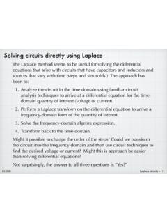
Solving circuits directly using Laplace
tuttle.merc.iastate.eduEE 230 Laplace circuits – 5 Now, with the approach of transforming the circuit into the frequency domain using impedances, the Laplace procedure becomes: 1. Transform the circuit. Use the Laplace transform version of the sources and the other components become impedances. 2. Solve the circuit using any (or all) of the standard circuit analysis

Experiment No. 9 WIEN BRIDGE OSCILLATOR USING OPAMP
ee.cet.ac.inElectronic Circuits Lab, Department of Electrical Engineering, College of Engineering Trivandrum 1 Experiment No. 9 WIEN BRIDGE OSCILLATOR USING OPAMP AIM: To design a Wien Bridge oscillator using op-amp for a given frequency of 1kHz. THEORY: An oscillator is a circuit that produces periodic electric signals such as sine wave or square wave.
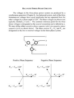
BALANCED THREE-PHASE CIRCUITS
my.ece.msstate.eduThe most efficient way to handle three-phase circuits containing delta sources and/or loads is to transform all delta connections into wye connections. Delta-Wye Source Transformation Given that a delta source is defined in terms of line-to-line voltages while the wye source is defined in terms of line-to-neutral voltages, we can use

Interface Circuits for TIA/EIA-644 (LVDS) (Rev. B)
www.ti.comInterface Circuits for TIA/EIA-644 (LVDS) 3 Receiver Sensitivity Levels 2.4 V 2 V Common-Mode Voltage 2.2 V 0.4 V 0 V Common-Mode Voltage 0.2 V Common-Mode Voltage 1.2 V 247 – 454 mV RECEIVER INPUT LEVELS DRIVER OUTPUT LEVELS 100 mV – 100 mV Receiver Sensitivity Levels 100 mV – 100 mV ±1 V Ground Noise Figure 2. Driver and Receiver ...
'Single-Supply Op Amp Design Techniques' - Texas …
www.ti.comUnless otherwise specified, all op amps circuits are single-supply circuits. The single supply may be wired with the negative or positive lead connected to ground, but as long as the supply polarity is correct, the wiring does not affect circuit operation. Use of a single-supply limits the polarity of the output voltage. When the supply

Thevenin / Norton equivalent circuits - Iowa State University
tuttle.merc.iastate.eduThevenin / Norton equivalent circuits We have seen many instances where we can take elements in a part of a circuit and combine them in some fashion to make an equivalent circuit. With respect to the two terminals, the two versions behave identically. Anything attaching to the two terminals will not be able to tell the difference. R eq = R 1 +R ...

Basic Electronics
engineering.nyu.eduis built using a transformer and a full-wave rectifier. •Transformer is used to step down the voltage i/p. •Rectifier converts AC to pulsed DC. •A filter capacitor is used to smooth out the pulses. •Capacitor must be large enough to store sufficient charge so as to provide a steady current supply to the load:
Lecture Notes for Digital Electronics - University of Oregon
pages.uoregon.eduusing purely digital techniques. Examples are numbers and words. The drawback to digitization is that a single analog signal (e.g. a voltage which is a function of time, like a stereo signal) needs many discrete states, or bits, in order to give a satisfactory reproduction. For example, it requires a minimum of 10 bits to determine a