Transcription of 'Single-Supply Op Amp Design Techniques' - Texas …
1 single SupplyOpAmpDesignTechniquesMarch 2001 Mixed Signal ProductsApplicationReportSLOA030 AIMPORTANT NOTICET exas Instruments and its subsidiaries (TI) reserve the right to make changes to their products or to discontinueany product or service without notice, and advise customers to obtain the latest version of relevant informationto verify, before placing orders, that information being relied on is current and complete. All products are soldsubject to the terms and conditions of sale supplied at the time of order acknowledgment, including thosepertaining to warranty, patent infringement, and limitation of warrants performance of its products to the specifications applicable at the time of sale in accordance withTI s standard warranty. Testing and other quality control techniques are utilized to the extent TI deems necessaryto support this warranty.
2 Specific testing of all parameters of each device is not necessarily performed, exceptthose mandated by government are responsible for their applications using TI order to minimize risks associated with the customer s applications, adequate Design and operatingsafeguards must be provided by the customer to minimize inherent or procedural assumes no liability for applications assistance or customer product Design . TI does not warrant or representthat any license, either express or implied, is granted under any patent right, copyright, mask work right, or otherintellectual property right of TI covering or relating to any combination, machine, or process in which suchproducts or services might be or are used. TI s publication of information regarding any third party s productsor services does not constitute TI s approval, license, warranty or endorsement of information in TI data books or data sheets is permissible only if reproduction is withoutalteration and is accompanied by all associated warranties, conditions, limitations and notices.
3 Representationor reproduction of this information with alteration voids all warranties provided for an associated TI product orservice, is an unfair and deceptive business practice, and TI is not responsible nor liable for any such of TI s products or services with statements different from or beyond the parameters stated by TI forthat product or service voids all express and any implied warranties for the associated TI product or service,is an unfair and deceptive business practice, and TI is not responsible nor liable for any such see: Standard Terms and Conditions of Sale for Semiconductor Products. Address: Texas InstrumentsPost Office Box 655303 Dallas, Texas 75265 Copyright 2001, Texas Instruments Incorporatediii single supply Op Amp Design TechniquesContentsIntroduction 1.
4 circuit Analysis 3.. Simultaneous Equations 7.. Case1: VOUT = mVIN+b 8.. Case 2: VOUT = mVIN b 11.. Case 3: VOUT = mVIN + b 13.. Case 4: VOUT = mVIN b 16.
5 Summary 18.. List of Figures1 Split- supply Op Amp Circuit1.. 2 Split- supply Op Amp circuit With Reference-Voltage Input2.. 3 Split- supply Op Amp circuit With Common-Mode Voltage2.. 4 single - supply Op Amp Circuit2.. 5 Inverting Op Amp4.. 6 Inverting Op Amp With VCC Bias5.. 7 Transfer Curve for an Inverting Op Amp With VCC Bias5.. 8 Noninverting Op Amp6.. 9 Transfer Curve for Noninverting Op Amp6.. 10 Schematic for Case1: VOUT = mVIN + b8.. 11 Case 1 Example Circuit10.. 12 Case 1 Example circuit Measured Transfer Curve11.. 13 Schematic for Case 2; VOUT = mVIN b12.. 14 Case 2 Example Circuit13.. 15 Case 2 Example circuit Measured Transfer Curve13.. 16 Schematic for Case 3; VOUT = mVIN + b14.
6 17 Case 3 Example Circuit15.. 18 Case 3 Example circuit Measured Transfer Curve15.. 19 Schematic for Case 4; VOUT = mVIN b16.. 20 Case 4 Example Circuit17.. 21 Case 4 Example circuit Measured Transfer Curve17.. ivSLOA030A1 single - supply Op Amp Design TechniquesRon ManciniABSTRACTThis application report describes single - supply op amp applications, their portability andtheir Design techniques. The single - supply op amp Design is more complicated than aspilt- or dual- supply op amp, but single - supply op amps are more popular because of theirportability. New op amps, such as the TLC247X, TLC07X, and TLC08X have excellentsingle- supply parameters. When used in the correct applications, these op amps yieldalmost the same performance as their split- supply counterparts. The single - supply opamp Design normally requires some form of portable systems have one battery, thus, the popularity of portableequipment results in increased single supply applications.
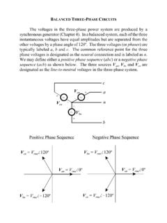
7 Split- or dual-supplyop amp circuit Design is straight forward because the op-amp inputs and outputsare referenced to the normally grounded center tap of the supplies. In the majorityof split- supply applications, signal sources driving the op-amp inputs arereferenced to ground. Thus, with one input of the op amp referenced to ground,as shown in Figure 1, there is no need to consider input common-mode ++VRF VVOUT = VINRGVIN RF RGFigure 1. Split- supply Op Amp CircuitWhen the signal source is not referenced to ground (see Figure 2), the voltagedifference between ground and the reference voltage shows up amplified in theoutput voltage. Sometimes this situation is okay, but other times the differencevoltage must be stripped out of the output voltage. An input-bias voltage is usedto eliminate the difference voltage when it must not appear in the output voltage(see Figure 3).
8 The voltage (VREF) is in both input circuits, hence it is named acommon-mode voltage. Voltage-feedback op amps, like those used in thisapplication note, reject common-mode voltages because their input circuit isconstructed with a differential amplifier (chosen because it has naturalcommon-mode voltage rejection capabilities).Introduction2 SLOA030A_++VRF VVOUT = (VIN + VREF)RGVINVREF RF RGFigure 2. Split- supply Op Amp circuit With Reference-Voltage Input_++VRF VVOUT = VINRGVINVREFRGRFVREFVREF RF RGFigure 3. Split- supply Op Amp circuit With Common-Mode VoltageWhen signal sources are referenced to ground, single - supply op amp circuitsexhibit a large input common-mode voltage. Figure 4 shows a single - supply opamp circuit that has its input voltage referenced to ground. The input voltage isnot referenced to the midpoint of the supplies like it would be in a split-supplyapplication, rather it is referenced to the lower power supply rail.
9 This circuit doesnot operate when the input voltage is positive because the output voltage wouldhave to go to a negative voltage, hard to do with a positive supply . It operatesmarginally with small negative input voltages because most op amps do notfunction well when the inputs are connected to the supply ++VRFVOUTRGVINF igure 4. single - supply Op Amp CircuitCircuit Analysis3 single - supply Op Amp Design TechniquesThe constant requirement to account for inputs connected to ground or otherreference voltages makes it difficult to Design single - supply op amp circuits. Thisapplication note develops an orderly procedure which leads to a working designevery time. If you do not have a good working knowledge of op amp equations,please reference the Understanding Basic series of application notesavailable from Texas Instruments. Application note SLAA068 titled,Understanding Basic Analog-Ideal Op Amps develops the ideal op ampequations.
10 circuit equations are written with the ideal op amp assumptions asspecified in Understanding Basic Analog-Ideal Op Amps; the assumptions aretabulated below for your NAMEPARAMETERS SYMBOLVALUEI nput currentIIN0 Input offset voltageVOS0 Input impedanceZIN Output impedanceZOUT0 Gaina Unless otherwise specified, all op amps circuits are single - supply circuits. Thesingle supply may be wired with the negative or positive lead connected toground, but as long as the supply polarity is correct, the wiring does not affectcircuit of a single - supply limits the polarity of the output voltage. When the supplyvoltage (VCC) = 10 V, the output voltage is limited to the range 0 VOUT 10. Thislimitation precludes negative output voltages when the circuit has a positivesupply voltage, but it does not preclude negative input voltages when the circuithas a positive supply voltage.