The Parallel Resonant
Found 11 free book(s)
The Parallel Resonant Converter
ecee.colorado.eduThe Parallel Resonant Converter he objective of this chapter is to describe the operation of the parallel resonant converter in detail. The concepts developed in chapter 3 are used to derive closed-form solutions for the output characteristics and steady …
Design Considerations for an LLC Resonant Converter
www.resonant-converters.euParallel Resonant (PR) converter The resonant inductor (Lr) and resonant capacitor (Cr) are in series The resonant capacitor is in parallel with the load 9The impedance of resonant tank can be changed by varying the frequency of driving voltage (V d) 7 1. Introduction Advantages
Ch4. LLC Resonant Converter - Virginia Tech
vtechworks.lib.vt.eduIt is called parallel resonant converter because in this case the load is in parallel with the resonant capacitor. More accurately, this converter should be called series resonant converter with parallel load. Since transformer primary side is a capacitor, an inductor is added on the secondary side to math the impedance. Figure 4.4 Half bridge ...

RLC Resonant Circuits - University of Cambridge
mlg.eng.cam.ac.uk3 Parallel Circuit Figure 5 shows a parallel resonant RLC circuit. It is the ‘dual’ of the series circuit in that the voltage and current exchange roles. This means that the circuit has a current gain rather than a voltage gain and that the impedance is 3.

Agilent Basics of Measuring the Dielectric Properties of ...
academy.cba.mit.eduResonant cavity .....25 Parallel plate .....27 Comparison of methods ... across a parallel plate capacitor, more charge is stored when a dielectric material is between the plates than if no material (a vacuum) is between the plates. The dielectric material increases the storage capacity of the capacitor

Quality factor, Q - UC Santa Barbara
web.ece.ucsb.eduWhen a resonant circuit is connected to the outside world, its total losses (let’s call them RP or GP) are combined with the source and load resistances, RS and RL. For example, Here is a parallel resonant circuit (C,L and RP)connected to the outside. The total Q of this circuit is called the loaded Q or QL and is given by
AN2867 Application note - STMicroelectronics
www.st.comis the anti-resonant frequency when impedance Z tends to infinity. Using equation (1), it is expressed as follows: Fa Fs 1 Cm C0 = + -----The region delimited by F. s. and F. a. is usually called the area of parallel resonance (shaded area in . Figure 2). In this region, the crystal operates in parallel resonance and behaves as
Crystal Oscillators (XTAL) - University of California ...
rfic.eecs.berkeley.eduSeries and Parallel Mode C 0 L 1 C 1 R 1 C 0 L 1 R 1 low resistance high resistance Due to the external physical capacitor, there are two resonant modes between a series branch and the capacitor. In the series mode ωs, the LCR is a low impedance (“short”). But beyond this frequency, the LCR is an equivalent inductor that resonates
Teaching the Difference Between Stiffness and Damping
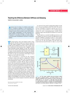
hfu.mech.utah.eduFactor”). For the parallel mass-spring-damper system, the Q factor at the resonant frequency is Q m. k c/ , where m is the mass, k is the spring constant, and c is the damping coefficient. Thus, increasing the spring constant k makes the behavior of the system more elastic and increases the Q factor, while decreasing the spring constant makes the

My Top Five Backyard Multi-Band Wire HF Antennas - …
www.qsl.net1/2-wavelength resonant center-fed dipoles have many other interesting characteristics, but the ones that we have noted will guide us while we explore the top 5 multi-band backyard wire antennas. We shall also be setting aside our coaxial cable in favor of parallel feedline to an antenna tuner (ATU) or, as

LLC Resonant Converter Using MC56F83783 - NXP
www.nxp.comcan be used to analyze the LLC resonant converter, the input-to-output voltage gain can be obtained as: Where, • • • • • fsw is the operating frequency. Figure 2 shows the input-to-output gain varies with fn under certain m and Qe. NXP Semiconductors System description LLC Resonant Converter Using MC56F83783, Rev. 0, 10/2019 ...