Using pwm to generate analog output
Found 9 free book(s)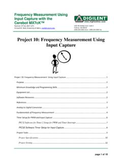
Project 10: Frequency Measurement Using Input …
www.mrc.uidaho.edu1. PIC32 Input Capture 2. Voltage to Frequency Converter 3. Using PWM to Generate Analog Output 4. C Programming Reference . Analog to Digital Conversion
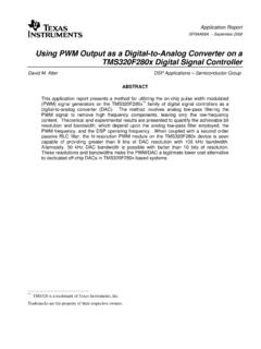
Using PWM Output as a Digital-to-Analog …
www.ti.comSPRAA88A Using PWM Output as a Digital-to-Analog Converter on a TMS320F280x Digital Signal Controller 7 Figure 4. Total Uncertainty in the D/A Output

Application Note Thermopile Module with Analog …
www.heimannsensor.come 1 7 Application Note Thermopile Module with Analog Outputs HEIMANN Sensor GmbH Grenzstr. 22 D-01109 Dresden Rohrbergstr. 7 D-65343 Eltville Managing Director
One Technology Way - Analog Devices
www.analog.comThe first issue is that secondary side voltage sensing is typically used with one main output of a converter. Secondary side voltage sensing can provide excellent voltage regulation (such as
Integrated Power Factor Correction (PFC) and …
ww1.microchip.com2008 Microchip Technology Inc. DS01208A-page 3 AN1208 A NOVEL APPROACH FOR DIGITAL IMPLEMENTATION OF PFC AND SENSORLESS FOC ALGORITHMS Figure 2 shows a block diagram of the PFC and Sensorless FOC control loops implemented digitally using the dsPIC DSC device.
Section 14. Motor Control PWM - Microchip …
ww1.microchip.com© 2007-2012 Microchip Technology Inc. DS70187E-page 14-5 Section 14. Motor Control PWM Motor Control PWM 14 • PxDC2: PWM Duty Cycle Register 2 The 16-bit PWM duty cycle value for the PWM output pair 2 is written into this register.
OneTechnologyWay P.O.Box9106 Norwood,MA ... - …
www.analog.comApplication Note AN-1319 Rev. 0 | Page 3 of 20 SYSTEM OVERVIEW In a battery formation and test system, each charge/discharge unit is comprised of three major components—an analog front

Pulse Width Modulation (PWM) Tutorial
electrathonoftampabay.orgThe ‘on/off’ PWM duty cycle: Starts with eight pulses ‘high’ for the first part of the PWM cycle, then finishes with eight ‘low’ pulses for the remainder of the PWM cycle.
Write your own generic SPICE Power Supplies …
www.intusoft.com1 Write your own generic SPICE Power Supplies controller models Christophe BASSO November 1996 Manuscript for PCIM US Simulating the switching behavior of a Switch Mode Power Supply (SMPS) is not always an easy task.
Similar queries
Project 10: Frequency Measurement Using Input, Using PWM to Generate Analog Output, Analog, Using PWM Output, Digital-to-Analog, Digital-to-Analog Converter on a TMS320F280x, Output, Application Note Thermopile Module with Analog, Application Note Thermopile Module with Analog Outputs, Analog Devices, Integrated Power Factor Correction (PFC) and, Using, Section 14. Motor Control PWM, PWM output, Pulse Width Modulation, Generic SPICE Power Supplies, Generic SPICE Power Supplies controller models