Search results with tag "Demodulator"
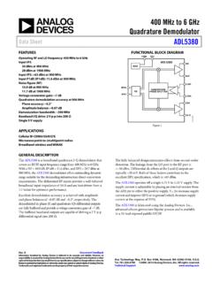
400 MHz to 6 GHz Quadrature Demodulator Data Sheet …
www.analog.comPHASE SPLITTER ADL5380 V2I BIAS LOIP LOIN IHI ILO QHI QLO 07585-001. Figure 1. GENERAL DESCRIPTION The ADL5380. is a broadband quadrature I-Q demodulator that covers an RF/IF input frequency range from 4 00 MHz to 6 GHz. With a NF = 10.9 dB, IP1dB = 11.6 dBm, and IIP3 = 29.7 dBm at 900 MHz, the ADL5380 demodulator offers outstanding …

Synchronous Demodulator and Configurable Analog Filter ...
www.analog.comSynchronous Demodulator and Configurable Analog Filter Data Sheet ADA2200 FEATURES Demodulates signal input bandwidths to 30 kHz Programmable filter enables variable ...

DC to 50 MHz, Quad I/Q Demodulator and Phase Shifter Data ...
www.analog.comDC to 50 MHz, Quad I/Q Demodulator and Phase Shifter Data Sheet AD8339 Rev. B Information furnished by Analog Devices is believed to be accurate and reliable.
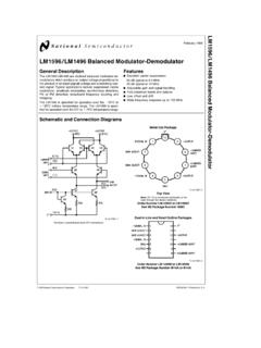
LM1596/LM1496 Balanced Modulator …
www.mit.eduTL/H/7887 LM1596/LM1496 Balanced Modulator-Demodulator February 1995 LM1596/LM1496 Balanced Modulator-Demodulator General Description The LM1596/LM1496 are doubled balanced modulator-de-
400 MHz to 6 GHz Quadrature Demodulator Data …
www.analog.com400 MHz to 6 GHz Quadrature Demodulator Data Sheet ADL5380 FEATURES Operating RF and LO frequency: 400 MHz to 6 GHz Input IP3 . 30 dBm at 900 MHz . 28 dBm at 1900 MHz

MC1496, MC1496B Balanced Modulators/ Demodulators
www.onsemi.comMC1496/D MC1496, MC1496B Balanced Modulators/ Demodulators These devices were designed for use where the output voltage is a product of an input voltage (signal) and a switching function (carrier). Typical applications include suppressed carrier and amplitude modulation, synchronous detection, FM detection, phase detection, and chopper ...

LTC5584 - 30MHz to 1.4GHz IQ Demodulator with IIP2 and …
www.analog.comquadrature phase shifter. In addition, the LTC5584 provides four analog control voltage interface pins for IIP2 and DC offset correction, greatly simplifying system calibration. The high linearity of the LTC5584 provides excellent spur-free dynamic range for the receiver. This direct conversion demodulator can eliminate the need for ...

IQ Demodulator datasheet (Rev. A) - TI.com
www.ti.comwww.ti.com THERMAL CHARACTERISTICS TRF3710 SLWS199A–AUGUST 2007–REVISED FEBRUARY 2008 TERMINAL FUNCTIONS TERMINAL I/O DESCRIPTION NAME NO. AGND 26, 35 Analog ground; grounds can be tied together.

User Manual - RF Demodulator
www.cleanrf.com1 1 User Manual Connections and Applications Table of contents: Introduction - Identifying the Problem Connections - Making the …
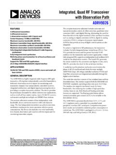
Integrated, Quad RF Transceiver with Observation Path …
www.analog.comMultichip phase synchronization for all local oscillators and baseband clocks . ... demodulator device. The ADRV9026 is powered directly from 1.0 V, 1.3 V, and ... I/Q rate = 245.76 MHz, transmitter = 200 MHz large signal bandwidth plus 450 MHz synthesis bandwidth, I/Q rate = 491.52 MHz, observation receiver (OR ...

MC1496, MC1496B Balanced Modulators/ Demodulators
www.onsemi.comMC1496, MC1496B http://onsemi.com 5 Bias currents flowing into Pins 1, 4, 8 and 10 are transistor base currents and can normally be neglected if external bias

MODEL SR830
www.thinksrs.comPhase Noise External synthesized reference: 0.005° rms at 1 kHz, 100 ms, 12 dB/oct. Internal reference: crystal synthesized, <0.0001° rms at 1 kHz. Phase Drift <0.01°/°C below 10 kHz <0.1°/°C to 100 kHz Harmonic Detect Detect at Nxf where N<19999 and Nxf<102 kHz. Acquisition Time (2 cycles + 5 ms) or 40 ms, whichever is greater. DEMODULATOR
Chapter 8 Frequency Modulation (FM) Contents
user.eng.umd.eduSlide 13 Phase-Locked Loop Demodulator Slide 14 PLL Analysis Slide 15 PLL Analysis (cont. 1) Slide 16 PLL Analysis (cont. 2) Slide 17 Linearized Model for PLL Slide 18 Proof PLL is a Demod for FM Slide 19 Comments on PLL Performance Slide 20 FM PLL vs. Costas Loop Bandwidth.
DEMODULATION - INAOE
www-elec.inaoep.mx3. Describe fm demodulation circuit operation for the phase-shift and gated-beam discriminators and the ratio-detector demodulator. 4. Describe phase demodulation circuit operation for the peak, low-pass filter, and conversion detectors. INTRODUCTION In chapters 1 and 2 you studied how to apply intelligence (modulation) to an rf-carrier wave ...

Clock (CLK) Jitter and Phase Noise Conversion ...
pdfserv.maximintegrated.comFigure 4. Practical phase-noise measurement setup. The structure described in Figure 4 is typically called a carrier-suppress demodulator. In Figure 4, n(t) is the input to the spectrum analyzer. We will next show that by scaling down the spectrum of n(t) properly, we can obtain the dBc value of L(f). Relation between RMS Period Jitter and ...
RF Power Amplifier Design - RFsilicon
www.rfsilicon.comQ I Q I Q modulator demodulator OPAs main amp. local oscillator RF-output bas eba nd i nput UMTS example: 40 Digital Predistortion ... phase-signal have higher than transmit signal-30 -20 -10 0 10 20 30-60-50-40-30-20-10 0 10 r e l a t i v e pow er / dB relative frequency / MHz Magnitude Phase

AD630 (Rev. G) - Analog Devices
www.analog.comBalanced Modulator/Demodulator Data Sheet AD630 Rev. G Document Feedback Information furnished by Analog Devices is believed to be accurate and reliable.
Similar queries
Demodulator, Phase, Q demodulator, Synchronous Demodulator and Configurable Analog Filter, Synchronous Demodulator and Configurable Analog Filter Data, Demodulator and Phase Shifter Data, Demodulator and Phase Shifter Data Sheet AD8339, Analog Devices, LM1596/LM1496 Balanced Modulator, LM1596/LM1496 Balanced Modulator-Demodulator, LM1596, LM1496, Balanced modulator, GHz Quadrature Demodulator Data, GHz Quadrature Demodulator Data Sheet ADL5380, MC1496, MC1496B Balanced Modulators/ Demodulators, MC1496, Phase shifter, IQ Demodulator, User Manual, Quad RF Transceiver with Observation Path, Modulation, And Phase, RF Power Amplifier Design