Transcription of 1.5 A max constant current LED driver - st.com
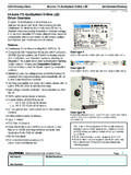
1 July 2008 Rev 81 A max constant current LED driverFeatures Up to 40 V input voltage Less than V voltage overhead Up to A output current PWM dimming pin Shutdown pin LED disconnection diagnosticApplications Supplying LEDs with constant current for varying input voltages Low voltage lighting Small appliance LED lighting Car LED lightsDescriptionThe STCS1 is a BiCMOS constant current source designed to provide a precise constant current starting from a varying input voltage source. The main target is to replace discrete components solution for driving LEDs in low voltage applications such as 5 V, 12 V or 24 V giving benefits in terms of precision, integration and current is set with external resistor up to A with a 10 % precision; a dedicated pin allows implementing PWM open-drain pin output provides information on load disconnection (3x3 mm) Table summaryOrder codesPackagesPackagingSTCS1 PURDFN8 (3 x 3 mm)3000 parts per reelSTCS1 PHRP owerSO-82500 parts per diagram.
2 32 Pin configuration .. 43 Maximum ratings .. 54 Electrical characteristics .. 65 Timing .. 76 Typical performance characteristics .. 87 Detail description .. setting .. dimming .. 98 Application information .. polarity protection .. considerations .. 109 Package mechanical data .. 1210 Revision history .. 16 STCS1 Application diagram3/171 Application diagram Figure application diagram for A LED current to ohmLoad disconnection(Open Drain output)OFFOFFONONPWMENGNDVCCDISCFBDRAINR IN100 to ohmLoad disconnection(Open Drain output)OFFOFFONONPWMENGNDVCCDISCFBDRAINR IN100 ohmBAT46 ZFILMPin configurationSTCS14/172 Pin configuration Figure connections (top view) DFN8 PowerSO-8 Table 2.
3 Pin descriptionPin n SymbolNote1 VCCS upply voltage2 PWMPWM dimming input3 ENShutdown pin4 DRAINI nternal N-MOSFET drain5 FBFeedback input. The control loop regulates the current in such a way that the average voltage at the FB input is 100 mV (nominal). The cathode of the LED and a resistor to ground to set the LED current should be connected at this order to guarantee the device works properly it is mandatory to leave this pin floating8 DISCLoad disconnection flag (open drain)Exp-padInternally connected to groundSTCS1 Maximum ratings5/173 Maximum ratings Note:Absolute maximum ratings are those values beyond which damage to the device may occur. Functional operation under these conditions is not maximum ratingsSymbolParameterValueUnitVCCDC supply to +45 VDRAIND rain to +45 PWM, EN, DISCL ogic to + VCC + to + body model (all pins) 2kVTJ (1)1.
4 TJ is calculated from the ambient temperature TA and the power dissipation PD according the following formula: TJ = TA + (PD x RthJA). See Figure 12 and Figure 13 for details of max power dissipation for ambient temperatures higher than 25 temperature-40 to 150 CTSTGS torage temperature range-55 to 150 CTable dataSymbolParameterDFN8 PowerSO-8 UnitRthJCThermal resistance junction-case1012 C/WRthJAThermal resistance (1)45 (2) C/W1. This value is referred to four-layer PCB, JEDEC standard test With two sides, two planes PCB following EIA/JEDEC JESD51-7 characteristicsSTCS16/174 Electrical characteristicsNote:All devices 100 % production tested at TA = 25 C. Limits over the operating temperature range are guaranteed by characteristics(VCC = 12 V; IO = 100 mA; TJ = -40 C to 125 C; VDRAIN = 1 V; CDRAIN = 1 F; CBYP = 100 nF typical values are at TA = 25 C, unless otherwise specified)SymbolParameterTest voltage current range11500mAIOO utput current RFB = 500mARegulation (percentage with respect to VCC=12V)VCC = to 40 V, IO = 100 mA; VDRAIN = 1 V-1+1%VFBF eedback voltageIO = 0 to current (Measured on VCC pin)On Mode450750 AShutdown Mode;VCC = 5 to 12V1 Shutdown Mode;VCC = 12 to 40V3 VDROPD ropout voltage (VDRAIN to GND)IO = 100 = leakage currentShutdown.
5 VDRAIN = 40 V10 ATDD elay on PWM signal (see Figure 3)VPWM rising, VCC = 12 V3 sVPWM falling, VCC = 12 level voltageISINK = 5 currentVDISC = 5 V1 ALoad disconnection threshold (VDRAIN-GND) DISC Turn-ON75mVDISC Turn-OFF110 ThermalProtectionShutdown temperature155 CHysteresis25 Logic inputs (PWM and EN)VLInput low high , PWM leakage current VEN = 5 V; VPWM = 5 V2 AEN input leakage currentVEN = 40 V60 PWM input leakage currentVPWM = 40 V120 STCS1 Timing7/175 TimingFigure and output current timing PWM10%90%TDTriseTDTfallCurrentPWM10%90%T DTriseTDTfallCurrentFigure diagram High Voltage 45 V+-+-DriverDisc compDISCDRAINFB75 mVEnable&PWML ogicShutdown all blocksThermal ShutdownLow Voltage 45 V100 mVCompLogicVCCENPWMGNDHigh Voltage 45 V+-+-+-+-DriverDisc compDISCDRAINFB75 mVEnable&PWML ogicShutdown all blocksThermal ShutdownThermal ShutdownLow Voltage 45 V100 mV100 mVCompLogicVCCENPWMGNDGNDT ypical performance characteristicsSTCS18/176 Typical performance characteristicsFigure vs VCC, TA = 25 CFigure vs RSET Figure vs temperatureFigure (including VFB)
6 Vs temperature Figure vs temperatureFigure 10. ICC vs VCC STCS1 Detail description9/177 Detail descriptionThe STCS1 is a BiCMOS constant current source designed to provide a precise constant current starting from a varying input voltage source. The main target is to replace discrete components solution for driving LEDs in low voltage applications such as 5 V, 12 V or 24 V giving benefits in terms of precision, integration and current settingThe current is set with an external sensing resistor connected to the FB pin. The feedback voltage is 100 mV, then a low resistor value can be chosen reducing power dissipation. A value between 1 mA and A can be set according to the resistor value, the resulting output current has a tolerance of 10 %.
7 For instance, should one need a 700 mA LEDs current , RF should be selected according to the following equation: RF = VFB / ILEDs = 100 mV / 700 mA = 142 m EnableWhen the enable pin is low the device completely off thus reducing current consumption to less than 1 A. When in shutdown mode, the internal main switch is PWM dimmingThe PWM input allows implementing PWM dimming on the LED current ; when the PWM input is high the main switch will be on and vice versa. A typical frequency range for the input is from few hertz to 50 kHz. The maximum dimming frequency is limited by the minimum rise/fall time of the current which is around 4 s each. Above 50 kHz the current waveforms starts assuming a triangular the PWM input is switching, the overall circuitry remains on, this is needed in order to implement a short delay time TD (see Figure 3).
8 Since the PWM pin is controlling just the main switch, the overall circuitry is always on and it is able to control the delay time between the PWM input signal and the output current in the range of few s, this is important to implement synchronization among several light LED DiagnosticWhen STCS1 is in on mode (EN is high), the device is able to detect disconnection or fail of the LED string monitoring VDRAIN pin. If VDRAIN is lower than 75 mV the DISC pin is pulled low regardless the PWM pin status. This information can be used by the system to inform that some problem happens in the informationSTCS110/178 Application Reverse polarity protectionSTCS1 must be protected from reverse connection of the supply voltage. Since the current sunk from VCC pin is in the range of 450 A a small diode connected to VCC is able to protect the chip.
9 Care must be taken for the whole application circuit, especially for the LEDs, in fact, in case a negative voltage is applied between VIN and GND, a negative voltage will be applied to the LED string that must have a total breakdown voltage higher than the negative applied voltage in order to avoid any Thermal considerationsThe STCS1 is able to control a LED current up to A and able to sustain a voltage on the drain pin up to 40 V. Those operating conditions are however limited by thermal constraints, the thermal resistances shown in the Table 4: Thermal data section are the typical ones, in particular RthJA depends on the copper area and the number of layers of the printed circuit board under the pad. DFN8 and PowerSO-8 have an exposed die attach pad which enhances the thermal conductivity enabling high power power dissipation in the device can be calculated as follow:PD = (VDRAIN - VFB) x ILED + (VCC x ICC)basing on this and on the thermal resistance and ambient temperature, the junction temperature can be calculated as:TJ = RthJA x PD + TAA typical application could be: Input Voltage: 12 V; 3 white LEDs with an typical VF = V; LEDs current : 500 mA;Figure 11.
10 Reverse polarity condition PWMENGNDVCCDRAINDISCFBVIN+or similarBAT46 PWMENGNDVCCDRAINDISCFBVIN+or similarBAT46 STCS1 Application information11/17 Package: DFN8 3x3 mm; TA = 50 C;In this case VDRAIN = 12 - 3 x = VPD = ( - ) x + 12 x x 10-3 = + 6 x 10-3 = 556 mWThe junction temperature will be:TJ = x + 50 = following pictures show the maximum power dissipation according to the ambient temperature for both packages:Figure 12. Maximum power dissipation vs TA for DFN8 3x3 mmFigure 13. Maximum power dissipation vs TA for PowerSO-8 RthJA= 38 [ C/W] [ C]PDMAX[W]PDMAX = (TJMAX-TA)/RthJARthJA= 38 [ C/W] [ C]PDMAX[W]PDMAX = (TJMAX-TA) [ C]PDMAX = (TJMAX-TA)/RthJARthJA= 45 [ C/W]PDMAX[W] [ C]PDMAX = (TJMAX-TA)/RthJARthJA= 45 [ C/W]PDMAX[W]Package mechanical dataSTCS112/179 Package mechanical dataIn order to meet environmental requirements, ST offers these devices in ECOPACK packages.