Transcription of 1-Wire 4Kb EEPROM
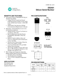
1 AVAILABLEF unctional DiagramsPin Configurations appear at end of data Diagrams continued at end of data is a trademark of Maxim Integrated Products, pricing, delivery, and ordering information, please contact Maxim Direct at 1-888-629-4642, or visit Maxim s website at DescriptionThe DS24B33 is a 4096-bit, 1-Wire EEPROM orga-nized as 16 memory pages of 256 bits each. Data iswritten to a 32-byte scratchpad, verified, and thencopied to the EEPROM memory. The DS24B33 commu-nicates over a single-conductor 1-Wire bus. The com-munication follows the standard 1-Wire protocol. Eachdevice has its own unalterable and unique 64-bit regis-tration number that is factory programmed into the registration number is used to address the devicein a multidrop 1-Wire net environment. The DS24B33 issoftware compatible to the of Calibration ConstantsBoard IdentificationStorage of Product Revision StatusFeatures 4096 Bits of Nonvolatile EEPROM Partitioned IntoSixteen 256-Bit Pages Read and Write Access is Highly Backward-Compatible to the DS2433 256-Bit Scratchpad with Strict Read/WriteProtocols Ensures Integrity of Data Transfer Unique, Factory-Programmed, 64-Bit RegistrationNumber Ensures Error-Free Device Selection andAbsolute Part Identity Switchpoint Hysteresis to Optimize Performancein the Presence of Noise Communicates to Host at or 125kbpsUsing 1-Wire Protocol Low-Cost Through-Hole and SMD Packages Operating Range: + to + , -40 C to +85 C IEC 1000-4-2 Level 4 ESD Protection ( 8kVContact, 15kV Air, Typical) for IO Pin1-Wire 4Kb EEPROMO rdering InformationIORPUPVCC CGNDDS24B33 Typical Operating CircuitNote.
2 The leads of TO-92 packages on tape and reel are formedto approximately 100-mil ( ) spacing. For details, refer tothe package outline drawing.+Denotes a lead(Pb)-free/RoHS-compliant = Tape and reel.*EP = Exposed TEMP RANGE PIN-PACKAGE DS24B33+ -40 C to +85 C TO-92 DS24B33+T&R -40 C to +85 C TO-92 DS24B33G+T&R -40 C to +85 C 2 SFN ( pcs) DS24B33Q+T&R -40 C to +85 C 6 TDFN-EP* ( pcs) DS24B33S+ -40 C to +85 C 8 SO (208 mils) DS24B33S+T&R -40 C to +85 C 8 SO (208 mils) 1-Wire is a registered trademark of Maxim Integrated Products, ; Rev 3; 5/12DS24B331-Wire 4Kb EEPROMABSOLUTE MAXIMUM RATINGSELECTRICAL CHARACTERISTICS(TA= -40 C to +85 C.) (Note 1)Stresses beyond those listed under Absolute Maximum Ratings may cause permanent damage to the device.
3 These are stress ratings only, and functionaloperation of the device at these or any other conditions beyond those indicated in the operational sections of the specifications is not implied. Exposure toabsolute maximum rating conditions for extended periods may affect device Voltage Range to GND .. to +6 VIO Sink Temperature Range ..-40 C to +85 CJunction Temperature ..+150 CStorage Temperature Range ..-55 C to +125 CLead Temperature (soldering, 10s) ..+300 CSoldering Temperature (reflow)TO-92 ..+250 CAll other packages, excluding SFN ..+260 CPARAMETER SYMBOL CONDITIONS MIN TYP MAX UNITS IO PIN: GENERAL DATA 1-Wire Pullup Voltage VPUP (Notes 2, 3) V 1-Wire Pullup Resistance RPUP (Notes 2, 4) k Input Capacitance CIO (Notes 5, 6) 2000 pF Input Load Current ILIO at VPUPMAX 5 A High-to-Low Switching Threshold VTL(Notes 6, 7, 8) VPUP - VInput Low Voltage VIL (Notes 2, 9) V Low-to-High Switching Threshold VTH (Notes 6, 7, 10) VPUP - VSwitching Hysteresis VHY (Notes 6, 7, 11) V Output Low Voltage VOL At 4mA (Note 12)
4 V Standard speed 5 Overdrive speed 2 VPUP + 1 Directly prior to reset pulse 640 s5 Recovery Time (Notes 2, 13) tRECD irectly prior to reset pulse > 640 s 10 s Standard speed 65 Standard speed, VPUP + 61 Overdrive speed 8 Time-Slot Duration (Notes 2, 14) tSLOTO verdrive speed, VPUP + 7 s IO PIN: 1-Wire RESET, PRESENCE-DETECT CYCLES tandard speed, tREC before reset = 10 s 480 960 Standard speed, tREC before reset = 5 s 480 640 Reset Low Time (Note 2) tRSTLO verdrive speed 48 80 s Standard speed 15 60 Presence-Detect High Time tPDH Overdrive speed 2 6 s Standard speed 60 240 Presence-Detect Low Time tPDL Overdrive speed 8 24 s Standard speed 60 75 Presence-Detect Sample Time (Notes 2, 15) tMSP Overdrive speed 6 10 s 2 Maxim IntegratedDS24B331-Wire 4Kb EEPROMELECTRICAL CHARACTERISTICS (continued)(TA= -40 C to +85 C.)
5 (Note 1)PARAMETER SYMBOL CONDITIONS MIN TYP MAX UNITS IO PIN: 1-Wire WRITES tandard speed 60 120 Write-Zero Low Time (Notes 2, 16) tW0L Overdrive speed 6 16 s Standard speed 5 15 Write-One Low Time (Notes 2, 16) tW1L Overdrive speed 1 2 s IO PIN: 1-Wire READS tandard speed 5 15 - Read Low Time (Notes 2, 17) tRL Overdrive speed 1 2 - s Standard speed tRL + 15 Read Sample Time (Notes 2, 17) tMSR Overdrive speed tRL + 2 s EEPROM Programm ing Current IPROG (Note 18) 2 mA Programm ing Time tPROG (Note 19) 5 ms At +25 C 200,000 Write/Erase Cycles (Endurance) (Notes 20, 21) NCYAt +85 C (worst case) 50,000 Data Retention (Notes 22, 23, 24) tDR At +85 C (worst case) 40 Years Note 1:Limits are 100% production tested at TA= +25 C and/or TA= +85 C.
6 Limits over the operating temperature range and relevant supply voltage range are guaranteed by design and characterization. Typical values are not 2:System 3:When operating near the minimum operating voltage ( ), a falling edge slew rate of 15V/ s or faster is 4:Maximum allowable pullup resistance is a function of the number of 1-Wire devices in the system, 1-Wire recovery times,and current requirements during EEPROM programming. The specified value here applies to systems with only onedevice and with the minimum 1-Wire recovery times. For more heavily loaded systems, an active pullup such as that foundin the DS2482-x00 or DS2480B may be 5:Capacitance on the data pin could be 2500pF when VPUPis first applied. Once the parasite capacitance is charged, itdoes not affect normal 6:Guaranteed by design, characterization, and/or simulation only. Not production 7:VTL, VTH, and VHYare a function of the internal supply voltage, which is a function of VPUP, RPUP, 1-Wire timing, andcapacitive loading on IO.
7 Lower VPUP, higher RPUP, shorter tREC, and heavier capacitive loading all lead to lower values ofVTL, VTH, and 8:Voltage below which, during a falling edge on IO, a logic 0 is 9:The voltage on IO must be less than or equal to VILMAXat all times while the master is driving IO to a logic 0 10:Voltage above which, during a rising edge on IO, a logic 1 is 11:After VTHis crossed during a rising edge on IO, the voltage on IO must drop by at least VHYto be detected as logic 12:The I-V characteristic is linear for voltages less than + 13:Applies to a single DS24B33 attached to a 1-Wire 14:Defines maximum possible bit rate. Equal to 1/(tW0 LMIN+ tRECMIN).Note 15:Interval after tRSTL during which a bus master can read a logic 0 on IO if there is a DS24B33 present. The power-up presencedetect pulse could be outside this interval but will be complete within 2ms after 16: in Figure 11 represents the time required for the pullup circuitry to pull the voltage on IO up from VILto VTH.
8 The actualmaximum duration for the master to pull the line low is tW1 LMAX+ tF- and tW0 LMAX+ tF- , 17: in Figure 11 represents the time required for the pullup circuitry to pull the voltage on IO up from VILto the input highthreshold of the bus master. The actual maximum duration for the master to pull the line low is tRLMAX+ 18:Current drawn from IO during the EEPROM programming interval. The pullup circuit on IO should be such that during theprogramming interval, the voltage at IO is greater than or equal to VPUPMIN. If VPUPin the system is close to VPUPMIN, thena low-impedance bypass of RPUP, which can be activated during programming, may need to be VIEW (T&R VERSION)FRONT VIEWSIDE : THE SFN PACKAGE IS QUALIFIED FOR ELECTRO-MECHANICAL CONTACTAPPLICATIONS ONLY, NOT FOR SOLDERING. FOR MORE INFORMATION, REFER TOAPPLICATION NOTE 4132: ATTACHMENT METHODS FOR ELECTRO-MECHANICALSFN (208 mils)TOP VIEW+SFN(6mm 6mm )BOTTOM (3mm 3mm)TOP VIEW24B33ymrrF+*EP*EXPOSED PADELECTRICAL CHARACTERISTICS (continued)(TA= -40 C to +85 C.)
9 (Note 1)Note 19:The tPROG interval begins after the trailing rising edge on IO for the last time slot of the E/S byte for a valid copy scratch-pad sequence. The interval ends once the device s self-timed EEPROM programming cycle is complete and the currentdrawn by the device has returned from IPROGto 20:Write-cycle endurance is degraded as 21:Not 100% production tested; guaranteed by reliability monitor 22:Data retention is degraded as 23:Guaranteed by 100% production test at elevated temperature for a shorter time; equivalence of this production test to datasheet limit at operating temperature range is established by reliability 24: EEPROM writes can become nonfunctional after the data-retention time is exceeded. Long-time storage at elevated tem-peratures is not recommended; the device can lose its write capability after 10 years at +125 C or 40 years at +85 4Kb EEPROMPin Configurations4 Maxim IntegratedDS24B33 Detailed DescriptionThe DS24B33 combines 4Kb of data EEPROM with afully featured 1-Wire interface in a single chip.
10 Thememory is organized as 16 pages of 256 bits each. Avolatile 256-bit memory page called the scratchpadacts as a buffer when writing data to the EEPROM toensure data integrity. Data is first written to the scratch-pad, from which it can be read back for verificationbefore transferring it to the EEPROM . The operation ofthe DS24B33 is controlled over the single-conductor1-Wire bus. Device communication follows the standard1-Wire protocol. The energy required to read and writethe DS24B33 is derived entirely from the 1-Wire com-munication line. Each DS24B33 has its own unalterableand unique 64-bit registration number. The registrationnumber guarantees unique identification and is used toaddress the device in a multidrop 1-Wire net environ-ment. Multiple DS24B33 devices can reside on a com-mon 1-Wire bus and be operated independently ofeach other.