Transcription of 1010.D.01.00173 1 Programming Guide - English
1 PROGRAMMERINGSGIDS. CENTURION SYSTEMS (PTY) LTD HEAD OFFICE: TEL: +27 (0)11 699-2400, FAX: +27 (0)11 704-3412 or 462-6669. 148 EPSOM AVENUE, NORTH RIDING. BOX 506, CRAMERVIEW, 2060. SOUTH AFRICA. WEB: General Information e-mail: FOR TECHNICAL SUPPORT CONTACT: EAST RAND .. (011) 397-6401. DURBAN .. (031) 701-9583. D3/D5 Programming Guide NELSPRUIT .. (013) 752-8074/5. PRETORIA .. (012) 362-8819/8893. CAPE TOWN .. (021) 447-1295. PORT ELIZABETH .. (041) 581-6994/5. EAST LONDON .. (043) 743-4923. BLOEMFONTEIN.
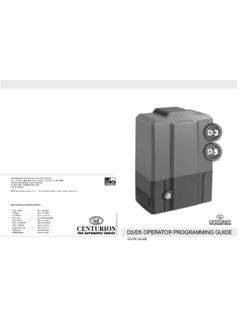
2 (051) 448-1714. KIMBERLEY .. (053) 832-3231. VEREENIGING.. (016) 422-5667. CENTURION. THE AUTOMATIC CHOICE D3/D5 OPERATOR Programming Guide . QUICK Guide . D3/D5 OPERATOR Programming Guide Programming MODE: 1 Disconnect electrical charge and negative wire to battery, from the controller card. Three points to consider before Programming the controller: 2 Position Set link over both Set Pins. 3 Replace all power to the controller card. 4 Ensure that L2 is ON (L1 must be OFF). 1 When the gate is in the CLOSED position the sensor magnet should be at least 500mm Release the Manual Override, move the gate to the half open position and re-engage Manual 5.
3 From the sensor. The gap between the sensor and the magnet must be between Override. 13 - 20mm. The arrow on the magnet must point in the direction of the sensor. 6 Press TEST button once. L1 will start flashing, once per second. L2 is OFF. 2 Wiring of the motor must be correct according to the gate opening direction. 7 Press and hold the TEST push button until the STATUS LED illuminates. Release TEST push button. Closing to the Left: Black wire to the outside. (Left of the Blue wire). The gate will start its automatic setup by OPENING.
4 At the OPEN endstop the gate will stop and Closing the the Right: Blue wire to the outisde. (Right of the Black wire). reverse slowly. At the CLOSED endstop the gate will stop and reverse. The gate will open quickly until the magnet reaches the origin sensor. When the gate reaches the origin sensor it will open 3 Ensure that you have effective endstops at both ends of the gate. slowly. At the OPEN endstop the gate will stop and reverse. The gate will close quickly until the (Refer to Installation manual) magnet reaches the origin sensor.
5 At the CLOSED endstop the gate will stop and reverse. The gate will open to the pedestrian opening point. 8 Press TEST push button once and release. Battery Terminals CP80. 9. 8 Ensure that L2 is ON (L1 should be OFF). This is the end of the automatic setup routine. L2. L1. AUTO CLOSE. Test Ensure controller is in Programming mode (L2 is ON). Status Press and hold the TEST button. L1 will start flashing; once pause, once - twice, when L1 flashes twice release the TEST push button. L1will continue to flash twice.
6 L2 will be OFF. Press TEST button and wait until the STATUS LED flashes once. Release TEST button. L2 will illuminate. AUTO CLOSE TIME is now ON and set to 15 seconds (Factory default). Remove the SET link from the set jumper and store the link on one of the pins of the jumper, if you want to exit program mode. Electrical Power Set Link Battery Power AUTO CLOSE TIME. CP80. Ensure that the controller is in Programming mode (L2 is ON). Press and hold TEST button. L1 starts flashing:1 pause, 1-2 pause 1-2-3-, release TEST button.
7 L1 continues to flash 3 times, press TEST button to set time (One flash of STATUS is equal to one second of auto-close time). Release the TEST button after the STATUS LED has flashed the required number of times. L2 will illuminate. AUTO CLOSE TIME is now set; remove the SET link from the set jumper and store the link on Sensor one of the pins of the jumper, if you want to exit the program mode. COLLISION SENSITIVITY. Ensure the controller is in Programming mode (L2 is ON). Press and hold the TEST button.
8 L1 starts flashing; 1 pause, 1-2 pause,1-2-3 pause, 1-2-3-4 pause, 1-2-3-4-5 pause, 1-2-3-4-5-6. Manual Override pause, 1-2-3-4-5-6-7, release TEST button. L1 continues flashing 7 times and L2 will go OFF. Press TEST button and wait for STATUS to flash;. 1 flash = High sensitivity (Gate stops easily). 1 pause, 1-2 = Medium sensitivity (Gate stop with reasonable effort). 1 pause, 1-2 pause, 1-2-3 = High sensitivity (Gate stops with difficulty). Release the TEST button after required number of flashes. L2 will go ON.
9 COLLISION SENSITIVITY is set; remove the SET link from the set jumper and store the link on one of the pins of the jumper, if you want to exit program mode.