Transcription of D3, D5, A5 SLIDING GATE AUTOMATION - …
1 Latest Revision: Ref.: Code: CP72SR5D3, D5, A5 SLIDING GATEAUTOMATIONINSTALLATIONMANUALMAJOR COMPONENTS (TYPICAL D5 SHOWN)- COVER- CONTROLLER (CP80 FOR D3/D5; CP81 FOR A5)- MOTOR (12V DC FOR D3/D5; 220V AC FOR A5)- BATTERY (12V DC, 7A/H-D3/D5 ONLY) (OR PSU1/2, IF FITTED)- CHARGER TRANSFORMER/POWER SUPPLY (CP84E for D3/D5 or CP83E for A5) (NOT FITTED WHEN PSU1/2 IS USED).- GEARBOX CASING- INTERNAL LIMIT SWITCH (DOSS)- MANUAL RELEASE THUMBWHEEL- LOCKABLE ACCESS DOOR103313233343536733836383430313233353 7 IOLLLEVEWARNING! (D5/A5 ONLY)Fill with oil prior to D3 is pre-filled with fluid Lift off the cover to the Remove the control card and battery so that you can gain access to the filler Unscrew the cap and pour in the oil providedFor transport purposes thisunit has been supplied withoil in a separate Specifications: GRADE: 75W90 Qty: 75mlIMPORTANTD3 gate MASS (kg)RUN (kgF)TABLE 1 START (kgF)2512300D56020500D5 Light Industrial16*16*500A5*LIMITED BY CAPACITY OF PSU22225002 ANTI-LIFT BRACKETS- Guide rollers must ensure that the gate is held Fit suitable anti-lift brackets.
2 The gap should be <5mm to ensure the gate cannot be lifted off the motor For improved safety fit additional support post to prevent gate from falling over if guide rollers *636414856678110081012141618202224262830 Pull ( kgf )Duty Cycle ( % )A5 with FAN5152030258020001004012060 Time (hrs)Duty Cycle ( % )A551520302580201004012060 Time (hrs)Duty Cycle ( % )DUTY CYCLE CURVES- FOR THE WARRANTY TO BE VALID, ENSURE THAT THE DUTY CYCLE IS NOT EXCEEDED FOR THE PARTICULAR MOTOR BEING USED. * - DUTY CYCLE IS SUBJECT TO BATTERY AND CHARGER For cable types to be used ( SWA, Cabtyre, Intercom cable etc.) consult your municipal authority for details.* n1 = NUMBER OF CORES REQUIRED BY INTERCOM# n2 = NUMBER OF CORES REQUIRED BY INTERCOM sufficient for motor only, increase to suit total load if pillar lights are fittedRECOMMENDED INSTALLATION AND CABLE THICKNESS REQUIREMENTS- LOCAL ISOLATOR- MAINS SUPPLY (min , 2 CORE + EARTH)- INTERCOM AND STATUS SIGNALING TO HOUSE ( , *n1 + 6 CORE)- INTERCOM TO gate STATION ( , #n2 CORES)- PILLAR LIGHTS ( , 2 CORE + EARTH)- RADIO RECEIVER ( , 3 CORE)- PEDESTRIAN KEYSWITCH ( , 2 CORE)- INFRA RED BEAM ( , 3 CORE)- FREE EXIT LOOP ( , multi stranded cable)- FREE EXIT CONTACT ( , 2 CORE)3245678910111126 MECHANICAL MOUNTING DETAILSO ption 1 - Bolt down onto concrete plinth- Ensure motor does not protrude into drive-way install baseplate with centre line 250mm off pillar Position baseplate (43) with centre of single support stud (45) 105mm from edge of gate (46).
3 (This dimension assumes centre line of rack (47) is 20mm from edge of gate ).- Using the baseplate as a template mark and drill the 4 mounting holes into the concrete for the four M10 x 95 expansion Use two M12 plated nuts per expansion stud as spacers below the foundation Secure the baseplate to the expansion studs using one M10 washer and nut per expansion NutUse two M12 platednuts as WasherM10 x 95 expansion studExisting concrete plinth- Ensure motor does not protrude into drive-way install baseplate with centre line 250mm off pillar centre. - Fasten concrete anchors (44) to the baseplate (43) using the M10x45 bolts provided. Ensure that the bolts are well Position baseplate (43) with centre of single support stud (45) 105mm from edge of gate (46). (This dimension assumes centre line of rack (47) is 20mm from edge of gate ).8105mm20mm4545434347474646LC444443 43m250m4444LC04m0m400mm300mmMECHANICAL MOUNTING DETAILSO ption 2 - Set into concrete plinthPROVISION FOR CABLES- Ensure cables are fitted through base plate before concreting in Remove knock-outs from gearbox to allow for cable Route cables in front of battery (D3/D5 motors) as shown Seal cable entry holes with silicone mm30 mm4643 GEARBOX MOUNTING DOWN DETAILS- Leave at least 7mm clearance between the lower gearbox nuts and the baseplate to allow for later Gearbox MUST be firmly located between top & bottom nuts and washers as shown at.
4 Use spring washer to lock top nut in Slide gearbox forwards or backwards to give 8mm clearance between front of pinion and edge of RACK- Attach steel rack to gate using 25x25x2mm angle brackets . Distance between centerline of rack and edge of gate should be 20mm (see ).- For best results support rack every Rack must be mounted level with a 2 - 3mm clearance .56555711555657 300 mmlRaise gearbox by an additional gearbox into manual mode (seeon page 22)lMesh rack and pinion fully and mount rack. Slide gate backwards and forwards ensuring that rack mesh is smooth and never gearbox by 3mm to create 3mm tooth TIP37 MOUNTING RACK CONTINUED200 - 300mmLEVEL200mm58605912- A simple way of ensuring correct pitch spacing when joining steel rack is to clamp a small offcut between the two Check that weld does not foul with meshing If RAZ rack is used, then start installing from the right hand side of the gate working towards the LHS.
5 Use fastening screws TEK screws at least every 200mm. 585960 INSTALLING CHAIN DRIVE SYSTEMS- Weld rear anchor plate onto gate such that centre line of tensioner pin is in line with top of the shaft on the idler pulley . Allow at least 100mm between idler pulleys and anchor Align fixed anchor bracket as for .- Ensure chain direction over sprocket is as shown (see ).IDLERPULLEYS13>100mm>100mm646562616361 6361656462 SETTING MECHANICAL CLUTCH (A5 ONLY)- Isolate MAINS Remove fan from motor to expose the motor shaft (where applicable). Ensure fan has stopped turning. - Lock shaft using 13mm spanner and use 6mm allen key to adjust sensitivity - Clockwise to increase Recommended maximum push force should not exceed <15kgF15- With the gate in the CLOSED position, mount the origin marker (66) a minimum 500mm from the origin sensor (68). (See isometric view (A) or plan view (B) above).
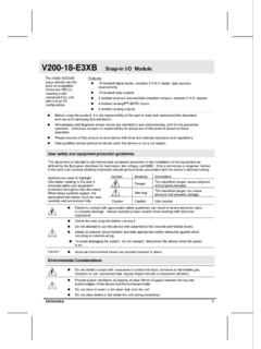
6 Please note this distance will affect the pedestrian opening distance. For minimum pedestrian opening, mount the origin marker at 500mm. The maximum distance of the origin marker is limited by the marker having to pass the sensor by no less than 500mm before the gate opens fully. If a longer crawling distance is required, the position of the marker needs to be changed (see table 3 on page 30).- Manually slide gate OPEN until origin marker (66) is in line with the origin sensor (68). Ensure distance between face of marker (66) and front face of sensor (68) is between 13 and 20mm. (See (C) above)- Adjust distance by SLIDING the origin marker (66) along the slotted mounting holes until desired distance is OF gate SENSOR66 BCCA6668 RTETHAN50mmGEAR 0 MOUNTING CONFIGURATIONFOR STEEL RACKORIGIN MARKERBRACKETWELDMOUNTINGBRACKETPROVIDED TOSTEEL RACKBOLT USINGFASTENERSPROVIDED666613-20mmGREATER THAN 500mm68 POWER WIRING (SEE PAGE 15 FOR SIGNAL WIRING)16- 220V AC MOTOR WITH STARTING CAPACITOR - 220V AC, 1 , MAINS SUPPLY FOR CP84E / CP83E USING REMOVABLE CONNECTORS- CP83E POWER SUPPLY TRANSFORMER (A5 MODEL ONLY)- 220V AC PILLAR LIGHT (NOT AVAILABLE ON CP84 XTE PSU)- 12V DC MOTOR- 12V DC LEAD ACID BATTERY (Amp/HOUR RATING TO SUIT)- CP84E CHARGER TRANSFORMER (D3/D5 MODEL) (OR CP84 XTE WHEN USED WITH PLUG-IN TRANSFORMER)- LIGHTNING EARTH POINT- 12V DC PLUG TO CP81 CONTROLLER- DC CHARGE PLUG TO CP80 CONTROLLER- PSU1/2 - POWER SUPPLY UNIT- MAINS FUSE - PSU1/2 NOTE.
7 External battery not necessary but if fitted then CP80 PSU1* controller must be fitted.*121314151617181920217576 LNE1212131520M1M3 LBROWNBLUEGREEN/YELLOWLIGHTCOMNEM2CP8119 14 NNLLEELNELNE1315211619 LIGHTLIGHTMOTORMOTORBATT -BATT +COM17 MCP80 NNLLEE181516 LIGHTLIGHTMOTORMOTORBATT -BATT +COM17 MCP80 PSU1*21 LNE137675 BATT -BATT +SIGNAL WIRING (CP80 AND CP81)COMCOMNEGNEGNEG2223242526272829N/CN /O12V12V12V17- RADIO RECEIVER (OR OTHER TRIGGER INTERCOM)- INFRA RED BEAM TRANSMITTER- INFRA RED BEAM RECEIVER (N/C CONTACT)- FREE EXIT TRIGGER (N/O CONTACT) - REMOTE STATUS LED (MAX 3 IN PARALLEL) - PEDESTRIAN TRIGGER (N/O CONTACT)- HOLIDAY LOCKOUT CONTROL (N/C LATCHING CONTACT)- REMOTE PILLAR LIGHT CONTROL (N/O CONTACT)LIGHTLIGHTCOMCOM+12 VTRGIRBFRXLEDLCKPEDSET= LED INDICATORS ON SHOWING STATUS OF INPUT SIGNALS = USE MULTI LED DRIVER CARD (CP78) FOR MORE LED SCP80 / CP812223245262272829 RECOMMENDED LIGHTNING PROTECTION18- For optimum lightning protection ensure earth cable from charger/PSU unit is adequately Use ring lug to bond to baseplate mounting For additional protection bond baseplate to earth spike.
8 - In event of damage to charger/PSU unit disconnect quick release link and push-on connector on AC OUTPUT220V ACINPUTTO CP80/CP81 PCB "DC IN LNE484334315034494850433449 COMMISSIONING BLOCK DIAGRAM19- Check correct motor direction (pg. 20)- Select programme mode (pg. 21)- Setting of gate limits (pg. 22-27) NOTE: D3/D5 LIMITS ARE SET AUTOMATICALLY. A5 LIMITS ARE SET MANUALLY- Function Selections(optional) (pg. 27-28)- Timer/counter settings (optional) (pg. 29-30)Steps 1 to 3 must be done on initial 4 & 5 are MOTOR DIRECTION20 ENSURE THAT MOTOR WIRE COLOURS ARE AS PER TABLE ABOVECP80 gate CLOSES: -aabbcTOWARDS LEFT (ABOVE)BLACKBLACKBLUEBLUEBLUEBLUEREDREDB LACKBLACKTOWARDS RIGHTCP81aTO 220V AC MOTORTO 12V DC MOTORbacCP80CP8112V DC220V ACMOTORM1M2M3bSELECTING PROGRAMME MODE21 STEP 1 - Remove power from control card: - for A5 remove electronics power only - for D3/D5 remove battery power as well as electronics power.
9 STEP 2 - Fit SET link .STEP 3 - Reapply power (reversal of STEP 1). STATUS LED will flash 5 times on power up. Check that LED L2 and SET are ON. LED L2 indicates controller is in programme mode .6970717269123 BLACKREDCP80 gate LIMITS22- Rotate manual release thumbwheel fully clockwise, or until clutch is fully dis-engaged and gate can be moved by ONLY- Slide gate approximately half way open. See above (FIG. 1).- Re-engage ONLY- Slide gate to fully closed position (FIG. 2).- Leave gearbox Skip to page 25-27 and follow START MANUAL gate LIMITS gate LIMITS (continued)23D3/D5 ONLY (PAGE 23, 24, 25)- Press the TEST pushbutton while monitoring LED When L1 flashes once, release TEST pushbutton. L2 will go out, L1 will continue to flash once per second. Controller is now in MENU 1 which sets gate Understand the procedure detailed on page 24 before continuing. The controller is about to perform the fully automatic setup Ensure you follow the correct procedure!
10 The procedure for setting D3/D5 and A5 motors is DIFFERENT. The A5 limits have to be set manually (see page 25 and 26), while the D3/D5 motors set their limits automatically (see page 21 to 23).CP80/CP81control cardL1L2 STATUSTESTSETSTART AUTOMATED gate LIMITS ROUTINE- Press TEST pushbutton until STATUS LED AUTOMATIC set up routine (described on page 24) starts as soon as TEST button is cardL1L2 STATUSTESTSET241234561- gate starts at crawl speed to open If gate closes, remove power and reverse motor wires (see page 20)2- gate hits open end stop and reverses direction running at crawl - gate hits closed end stop and reverses direction running at FULL speed until the marker, then at CRAWL speed to - gate hits open end stop and reverses but now runs at FULL - As gate sensor passes the motor, the speed reduces to CRAWL. gate hits closed end stops and reverses at FULL SPEED.