Transcription of D3&D5 SLIDING GATE AUTOMATION - Centurion …
1 Latest Revision: Ref.: Code: CP72 SLIDV3D3&D5 SLIDING GATEAUTOMATIONINSTALLATIONMANUALCENTURIO N SYSTEMS has been manufacturing automatic gate systems since 1987, and is committedto providing reliable, cost effective solutions in the field of access strives to give service and backup second to none. Our engineers are available to givesales support, installation training, and answers to technical or installation equipment is installed worldwide and is available through a network of is an ISO 9001 - 2000 registered company, continually looking at updating its products inline with world trends to ensure that its products will provide customer information is available on our web site part of this document may be copied, stored in a retrieval system or transmitted in any form or by any means electronic, mechanical, optical or photographic,without the express prior written consent of Centurion Systems (Pty) Ltd.
2 Centurion SYSTEMS (PTY) LTD 2005 CompanyProfileCompany ProfilePage 2 Centurion Systems (Pty) Ltd. reserves the right to make changes to the products described in this manual without notice and without obligation of CenturionSystems (Pty) Ltd. to notify any persons of any such revisions or changes. Additionally, Centurion Systems (Pty) Ltd. makes no representations or warranties withrespect to this ContentsTable of ContentsDeclaration of Safety Tools & Operator Cables and Secure Base the the the origin all into Programming the gate Limits (Automatic Set-Up Routine)..24 Exit Programming gate Additional Features (Optional)..27 Controller Programmable Terminal to Programme Controller Back to Factory Default Troubleshooting Finding Power Signal Charger Connection (Standard and Low Voltage)..42CP84 XTE Charger Power Earthing for Effective Lightning Controller Indicator 3 Declarationof ConformityDeclaration of ConformityPage 4 Manufacturer:Declares that the product:Conforms with the following specifications:For D3:Standard to which conformity is declared: Centurion Systems (Pty) Ltd148 Epsom AvenueNorth RidingGautengSouth AfricaProduct Name:D3 / D5 SLIDING gate OperatorProduct Options:All variantsSafety:IEC 60355-1:1991 & Am1:1994 & Am2:1999EN 12453:2000 EN 12978:2003 when fitted with CE chip and a P36 PassiveSensitive Edge according to :CISPR 14: 2nd edition 1985 CISPR 22 CLASS B: RADIATED EMISSIONS - 30 MHZ TO 1000 MHZCISPR 22 CLASS B: CONDUCTED EMISSIONS - 150 MHZ TO 30 MHZI mmunity:IEC 801-2: 2nd edition 1991 - 4kV CD, 8kV ADIEC 801-3: 1st edition 1984 - 10V/mIEC 801-4: 1st edition 1988 - Power LinesIEC 1000-3-2: 1997 IEC 1000-3-3: 1997 IEC 1000-4-5.
3 1997 IEC 61000-4-2 - ELECTROSTATIC DISCHARGEIEC 61000-4-3 - RADIATED IMMUNITY - 80 MHZ TO 1000 MHZIEC 61000-4-4 - ELECTRICAL FAST TRANSIENTS / BURSTIEC 61000-4-5 - SURGE IMMUNITY TESTIEC 61000-4-6 - CONDUCTED IMMUNITY - 150 KHZ TO 80 MHZIEC 61000-4-11 - VOLTAGE DIPS AND INTERRUPTIONS upply Information: The product herewith complies with the requirements fo the following directivesand carries the CE-marking the Low Voltage Directive 73/23/EEC- the EMC Directive 89/336/EEC (inclusive 93/68/EEC)]This product was tested in a typical configuration with simulated gate 60355-1:1991 & Am1: 1994 & Am2: 1999 IEC 1000-6-3 & IEC 1000-6-1: Generic Emission and ImmunitySigned at North Riding, South Africa on 15 August, 2005 Ian RozowskyTo ensure the safety of people, it is important that you read all thefollowing instructions. Incorrect installation or incorrect use ofthe product could cause serious harm to installer, being either professional or DIY, is the last person on the site that can ensure that theoperator is safely installed, and that the whole system can be operated FOR THE READ AND FOLLOW ALL INSTRUCTIONS before beginning to install the installation, repair, and service work to this productmust be done by a suitably qualified not activate your gate opener unless you can see it andcan determine that its area of travel is clear of people, pets,or other ONE MAY CROSS THE PATH OF A MOVING keep people and objects away from the gate andits area of LET CHILDREN OPERATE OR PLAY WITH THEGATE CONTROLS.
4 And do not allow children or pets nearthe gate all easily accessed gate opener controls in order toprevent unauthorized use of the not in any way modify the components of theautomated not install the equipment in an explosive atmosphere:the presence of flammable gas or fumes is a seriousdanger to attempting any work on the system, cut electricalpower and disconnect the The mains power supply of the automated system must befitted with an all-pole switch with contact opening distanceof 3mm or greater. Use of a 5A thermal breaker with all-pole circuit break is Make sure that an earth leakage circuit breaker with athreshold of 30mA is fitted upstream of the Never short circuit the battery and do not try to rechargethe batteries with power supply units other than thatsupplied with the product, or by Centurion Make sure that the earthing system is correctlyconstructed, and that all metal parts of the system aresuitably Safety devices must be fitted to the installation to guardagainst mechanical movement risks such as crushing,dragging and It is recommended that at least one warning indicator lightbe fitted to every Always fit the warning signs visibly to the inside andoutside of the The installer must explain and demonstrate the manualoperation of the gate in case of an emergency.
5 And musthand the User/Warnings guide over to the Explain these safety instructions to all persons authorizedto use this gate , and be sure that they understand thehazards associated with automated Do not leave packing materials (plastic, polystyrene, etc.)within reach of children as such materials are potentialsources of Dispose of all waste products like packaging materials,worn out batteries, etc, according to local obstruction detection system, andsafety devices for correct Centurion Systems does not accept any liability caused byimproper use of the product, or for use other than that forwhich the automated system was This product was designed and built strictly for the useindicated in this other use, notexpressly indicated here, could compromise the servicelife/operation of the product and/or be a source of Everything not expressly specified in these instructions isnot checkMOVING gate CAN CAUSESERIOUS INJURY OR DEATHKEEP CLEAR.
6 gate MAY MOVE ATANY TIME. DO NOT ALLOWCHILDREN TOOPERATE gate .PLAY IN AREA ORWARNINGPage 5 ImportantSafetyInstructionsImportant Safety InstructionsThese abbreviated instructions are for the experienced installer who needs a checklist to get astandard installation up and running in the minimum of installation features and functions are referred to later in this TrackActionMechanical SetupRead and understand all safety instructions5 Check site requirementsPage 12 Heed necessary site considerations14 Gather required tools and equipment14 Check cabling requirements15 Lubrication requirements16 Select method of mounting and operator positionPage 17 Route required cablingPage 18 Mount the operatorPage 19 Mount the rackPage 20 Mount the origin markerPage 22 Apply warning decalsPage 23 PagePagePagePagePageStep 1 Step 2 Step 3 Step 4 Step 5 Step 6 Step 7 Step 8 Step 9 Step 10 Step 11 Page 6 Read and understand all safety instructionsPage 5 Connect all wiring.
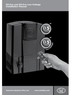
7 Page 24 Get into programming mode:Page 24 Remove all the SET the gate limits:Move gate half way and and hold TEST, release after 1 flash of and hold TEST, release after 1 flash that gate will travel in the correct programming mode:Page 27 Remove the SET gate operationPerform installation hand overPage 46 ActionElectrical SetupFastTrackFast TrackStep 2 Step 3 Step 4 Step 5 Step 6 Step 1 Page 7 When fault finding an existing installation, referto the FAULT FINDING GUIDE on page 35 Step 6 The D3 and D5 are SLIDING gate operators designed to open and close SLIDING D3 operator is suited to domestic applications with gates of a mass less than order to cater for high duty cycle installations, the D5 Light Industrial model is offered. The D5is similar to the Standard D5 model with the exception that it is rated for a higher dutycycle . It is suitable for sites with a gate mass up to 500kg, but can operate with a 50% duty travel limits are managed by an opto-electronic system, comprising a gate mounted origin markerand an internal rotary encoder.
8 This system yields precise and repeatable control over gate features of the CP80 logic controller include:-Automated setup of gate endpoints (limits).Fail safe collision detection and auto reverse (adjustable sensitivity).Smoothed start/stop (ramp up/down).Multiple operational , adjustable (partial) Close input for sensitive edge/safety beam/inductive lightning/surge courtesy light preflashing D5 operator is suited to domestic applications with gates of a mass less than modelIn cases where chain, (as opposed to toothed rack) drive is required, an optional chain drive kit isavailable.!!!!!!!!!!!Lightning ProtectionThe D5 electronic controller utilizes the same proven surge protection philosophy that is used in allCenturion products. While this does not guarantee that the unit will not be damaged in the event of alightning strike or power surge, it greatly reduces the likelihood of such damage occurring.
9 The earthreturn for the surge protection is provided via the mains power supply earth. In order to ensure that thesurge protection is effective, it is essential that the unit is properly 8 GeneralDescriptionGeneral DescriptionOverall DimensionsFigure 1 Overall DimensionsAll dimensions shown in millimetres2503453659840 Page 9 When fitting a theft resistant cage, the space required for aninstallation may have to be 10 SPECIFICATIONSD3D5 Maximum number of operations per day (Average)Mains Present:Standby;Maximum number of continuous operations per hour(Mains Present)Temperature range-10 to +50 C-10 to +50 CCorrosion protection (baseplate)ZincroshieldZincroshieldHousi ng protectionIP55IP55 Control card *CP80CP80 Mass of unit (packed) including 7,5Ah sensitivityElectronic, adjustable Electronic, adjustableEnd of travel controlSealed optical counterwith origin switchSealed optical counterwith origin switchTypical time to open/close a 4m gate17 seconds13 secondsWith 40Ah BatteryN/A100 With 7Ah Battery1210 Battery driven (1A charge, 7Ah battery)Battery driven (2A charger, 7Ah batteryPower pack (10A power pack, no battery)1030201030N/ABattery driven (1A charger, 7Ah battery)2050 Maximum gate mass300kg500kgRated Thrust12kgF20kgFStarting Thrust35kgF60kgFOutput shaft rotational speed73rpm91rpmDC Current draw (Max))
10 15A15 AAC Current draw @ 220V120mA120mAMotor Voltage12V DC12V DCPower Supply Voltage220V AC 10% 50Hz110V AC 10% 50Hz19V AC 10% 50Hz220V AC 10% 50Hz110V AC 10% 50Hz19V AC 10% 50Hz* D3 and D5 have different micro-controller versions11m11mMaximum gate lengthRated gate Speed (With gate pull force <5kg)16m/min20m/min(Depending on power supply used)30150 Battery driven (2A charger, 7Ah battery)N/A100 Power pack (10A power pack, no battery)The actual components supplied may vary depending on the model IdentificationFigure 2 Product IdentificationPart gate Origin Magnet Mounting KitD5 Magnetic Switch AssemblyWiring Harness DOSS & Sensor Plug17T Mod 4 Sintered Pinion S5 SlidersD3 17T Nylon 66 Pinion 8mm Radial PinD3 Gearbox Casing & Gear set AssemblyD5 Gearbox Casing & Gear set AssemblyD5 Gearbox OilSide Cover (Vertical) D5CP25SR5 D5 Foundation Plate AssemblyD3 Vent Cover (Logo)D5 Vent Cover (Logo)D5 Exterior CoverSupport Bracket D5 Slider (DOSS Side)Support Bracket D5 Slider (Battery Side)D5 Motor, 12V DC 3200 RPMD3 Motor 12V DC 2700 RPM1415161718192021222324252627282930109 9300700101026000010103701 ASCP80CP4 WHHCen-BATCP84E1099 SUB03A1010M11490101023000010102500001010 M101301050M02210MB44LA11071050M02220D5 KEYSPRCLIPCLID3 Drive Coupling (Motor Side)Mounting Plate D5CP80 EnclosureCP80 PC Board (Boxed)CP4 BatteryD5 Battery LeadsCP84E Power Supply (Boxed)DOSS Carrier AssemblyDOSS Mounting TubeSide Cover (Horizontal) D5Sr5 Door Hinge Pin 4 x 127mm 304 SSD5 Door V3 (Stiffened Lip)Camlock Cover Base19mm CamlockCamlock CoverSpare Key for D3/D5 MotorsCamlock Spring Clip(Includes harness)Page 11101116174a4b1820232430298762112141513a 13b9b9a21255a35b26272822 Starting Force1.
