Transcription of 117-12.pdf - Valve Lash Adjustment and Installation of the ...
1 1 17-12. 1 1 17-12. SUBJECT DATE. Valve Lash Adjustments and Installation of the Camshaft and Rocker Shaft/Engine Brake January 2012. Assembly Additions, Revisions, or Updates Publication Number / Title Platform Section Title Change Valve Lash Adjustments HDEP Valve Lash Adjustments and rocker DDC-SVC-MAN-0081 DD Platform Installation of the Camshaft and Rocker Shaft/ arm updates Engine Brake Assembly All information subject to change without notice. 3. 1 17-12 Copyright 2012 DETROIT DIESEL CORPORATION. 2 Valve Lash Adjustments 2 Valve Lash Adjustments Accurate Adjustment of clearance between intake and exhaust valves is important if maximum performance and economy are to be obtained. NOTICE: Failure to measure Valve clearances at the required initial period and make necessary adjustments may result in gradual degrading of engine performance and reduced fuel combustion efficiency.
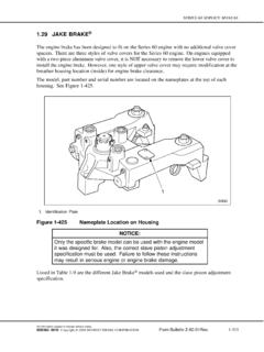
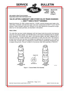
2 NOTE: Every time the Valve lash is adjusted the engine brake lash will also need to be set. NOTE: Adjust the Valve lash before setting the engine brake lash. 1. Turn engine OFF, (key OFF, engine OFF). 2. Steam clean the engine. 3. Disconnect the starting power for the engine. Refer to OEM procedures. 4. Remove the air cleaner and the turbocharger inlet pipe and hose. Refer to OEM procedures. 5. Remove air cleaner housing. Refer to OEM procedures. 6. Remove the rocker cover. Refer to section "Removal of the Rocker Cover". 7. Using special tool (J-46392), bar the engine over until cylinder number one is at Top Dead Center (TDC) compression stroke. 8. Using a feeler gauge (1), lash intake valves one, two and four to mm ( in.). a. Figure below displays the old style intake camshaft with 12 lobes and the old style rocker arms.
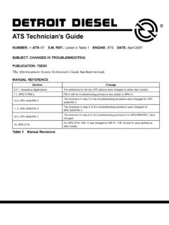
3 These components were utilized on DD13 engines built before engine serial number HDE0079072 and on the DD15 & DD16 engines built before HDE0077481. b. Figure below displays the new style intake camshaft with 6 lobes and bridged rocker arms. These components were installed on DD13 engines beginning with engine serial number HDE0079072 and on the DD15 &DD16 engines beginning with engine serial number HDE0077481. The components are not backwards compatible. 4 All information subject to change without notice. Copyright 2012 DETROIT DIESEL CORPORATION 1 17-12. 1 17-12. 9. Using a feeler gauge (1), lash exhaust valves one, three and five to mm ( in.). 10. Using special tool (J-46392), bar the engine over 360 until cylinder number six is at TDC compression stroke. 11. Lash intake valves three, five, and six to mm ( in.)
4 12. Lash exhaust valves two, four and six to mm ( in.). 13. Torque the locknut Valve adjusting screw to 50 N m (37 lb ft). 14. Remove any tools used for this procedure. 15. Set the engine brake lash. Refer to section "Setting the Engine Brake Lash". All information subject to change without notice. 5. 1 17-12 Copyright 2012 DETROIT DIESEL CORPORATION. 3 Installation of the Camshaft and Rocker Shaft/Engine Brake Assembly 3 Installation of the Camshaft and Rocker Shaft/Engine Brake Assembly Install as follows: Service Tools Used in the Procedure Tool Number Tool Name Engine W470589001500 TDC Locating Pin DD Platform W470589034000 Camshaft Timing Tool EPA07 DD13*. W470589114000 Camshaft Timing Tool EPA07/EPA10 DD13. W470589054000 Camshaft Timing Tool EPA07 DD15. W470589104000 DD15 Camshaft Timing Tool EPA07/EPA10 DD15/16.
5 W470589044000 Intake Rocker Arm Lifter/Spacer Tool DD13. W470589074000 Exhaust Rocker Arm Lifter/Spacer Tool DD13. W470589004000 Rocker Arm Lifter/Spacer Tool DD15/DD16. * Can be used on EPA10 with modification (refer to tool letter 10 TL-9). 1. Verify that the crankshaft is at top dead center (TDC) on cylinder number one by installing TDC Locating Pin in the crankshaft position sensor (CKP) hole located in flywheel housing. 2. Install camshaft timing tool to the rear of the camshaft housing. Tighten the two bolts. 6 All information subject to change without notice. Copyright 2012 DETROIT DIESEL CORPORATION 1 17-12. 1 17-12. 3. Locate the etched triangle on the camshaft gear teeth and mark the teeth with a paint pen. 4. Lubricate the lower camshaft bearing surfaces and camshaft journals before installing the camshafts.
6 Install the exhaust and intake camshaft gear assemblies into the camshaft housing. 5. Align the marked gear teeth with the marks on the timing tool. 6. Install the camshaft timing tool to the front of the camshaft housing and into the grooves cut into the camshafts. Secure timing tool to the camshaft housing with a bolt. a. At this point the front timing tool should slide into the camshaft grooves easily with no drag. b. If there is excessive drag when installing the tool, the camshafts are out of time. If so, repeat this procedure Go to step 3. 7. Verify that the marks on the gear teeth match the marks on the timing tool. NOTICE: The camshaft caps are numbered and need to be installed correctly. 8. Install the seven camshaft caps onto intake and exhaust camshafts. NOTICE: When installing the engine brake solenoids, do not use the bolt to pull the solenoid into the camshaft cap.
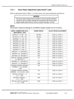
7 Damage will occur to the O-rings on the solenoid. All information subject to change without notice. 7. 1 17-12 Copyright 2012 DETROIT DIESEL CORPORATION. 3 Installation of the Camshaft and Rocker Shaft/Engine Brake Assembly 9. The first and seventh camshaft caps hold the engine brake solenoids to the camshaft cap. Replace the O-rings on the solenoids prior to reinstallation and lubricate with engine oil. Seat the engine brake solenoids into the camshaft caps by hand. NOTE: EPA07 DD15 uses 28 bolts to hold the camshaft cap and housing to the cylinder head. 10. Install the 30 bolts to camshaft caps; finger tighten the bolts. 11. Using the torque sequence shown below, torque the twenty one M10 camshaft cap bolts to the following: a. Torque all bolts to 20 N m (15 lb ft). b. Then torque to 50-55 N m (37-40 lb ft).
8 12. Using the torque sequence shown below, torque the nine 63 mm M8 bolts to 30 N m (22 lb ft). 13. Remove TDC locating pin from Crankshaft Position (CKP) sensor hole in the flywheel housing. 14. Install crankshaft position sensor. Refer to section " Installation of the Crankshaft Position Sensor". 15. Install a dial indicator onto gear case and zero out the dial indicator. 16. Position the stem of dial indicator to rest between the teeth on the camshaft gear. 17. Hold the number five idler gear with a screwdriver. Check the lash between the camshaft gear and idler gear number five. 8 All information subject to change without notice. Copyright 2012 DETROIT DIESEL CORPORATION 1 17-12. 1 17-12. NOTICE: The camshaft journal area is lubricated by oil that has to travel through the rocker shaft. If the rocker shaft is installed incorrectly, oil passages will not line up.
9 This results in insufficient lubrication and will damage the camshaft journals. Incorrect shaft Installation can also result in the engine brakes not functioning which will cause damage to the rocker arm bushings. NOTICE: The markings on the front of the rockers shafts must face the front of the engine for proper rocker arm lubrication and engine brake operation. NOTE: On EPA10 engines the intake and exhaust rocker shafts are each marked "TOP FRONT." Top Front must face towards the front of the engine. NOTICE: When tightening the rocker shaft bolts, ensure that the bolts are drawn down from the inside bolts outward, in 1/2 turn increments, before final torque. The rocker shaft can break if the rocker shaft bolt is fully torqued without using the increment procedure. 18. The dial indicator should read - mm ( - in.)
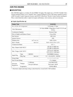
10 If the gear lash is excessive between the exhaust or intake camshaft gear and the number five idler gear, inspect the number five idler gear spindle, camshaft gear and camshaft housing. Repair as necessary. All information subject to change without notice. 9. 1 17-12 Copyright 2012 DETROIT DIESEL CORPORATION. 3 Installation of the Camshaft and Rocker Shaft/Engine Brake Assembly 19. Remove timing tools. 20. Using the Intake Rocker Arm Lifter / Spacer tool, install the intake rocker shaft assembly to the camshaft cap and secure with seven clamping blocks and bolts. 21. Using the torque sequence shown below, torque the bolts to 50-55 N m (36-41 lb ft) +90 . a. Figure below displays the old style intake rocker arm used on DD13 prior to engine serial number HDE0079072. and the DD15 & DD16 prior to engine serial number HDE0077481.