Transcription of 25 - Talking Electronics
1 662 Principles of ElectronicsINTRODUCTIONH istorically, an operational amplifier (OP-Amp) was designed to perform suchmathematical operations as addition,subtraction, integration and differentiation. Hence,the name operational amplifier . An operationalamplifier is a multistage amplifier and consists of adifferential amplifier stage, a high-gain CE amplifierstage and class B push-pull emitter follower. Anoperational amplifier (OP-Amp) is an *integratedcircuit and is widely used in computers, as video andaudio amplifiers in communication of their multi-purpose use, OP-Amps are*All the components of an OP-Amp ( , transistors,resistors etc.) are fabricated on a small chip calledintegrated circuit. amplifier Circuit of Differential amplifier and Differential-mode signals Gains of Analysis of DifferentialAmplifier (DA) of DA (or Op amp) dueto Mismatch of Analysis of amplifier (OP- Amp) Voltage from of an Response of an of and Output Impedance ofInverting of Negative Feedback on OP-Amp of OP-AMP of Summing CircuitsOperationalAmplifiers25 operational Amplifiers 663used in all branches of Electronics , both digital and linear circuits.
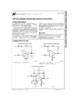
2 In this chapter, we shall discussthe various aspects of operational operational AmplifierAn operational amplifier (OP-Amp) is a circuit that can perform such mathematical operations asaddition, subtraction, integration and shows the block diagram of an operational amplifier . Note that OP-Amp is amultistage amplifier . The three stages are : differential amplifier input stage followed by a high-gainCE amplifier and finally the output stage. The key electronic circuit in an OP-Amp is thedifferential amplifier . A differential amplifier (DA) can accept two input signals and amplifies thedifference between these two input following points may be noted about operational amplifiers (OP-Amps) :(i)The input stage of an OP-Amp is a differential amplifier (DA) and the output stage istypically a class B push-pull emitter follower.
3 (ii)The internal stages of an OP-Amp are direct-coupled , no coupling capacitors are direct coupling allows the OP-Amp to amplify as well as signals.(iii)An OP-Amp has very high input impedance (ideally infinite) and very low outputimpedance (ideally zero). The effect of high input impedance is that the amplifier willdraw a very small current (ideally zero) from the signal source. The effect of very lowoutput impedance is that the amplifier will provide a constant output voltage independentof current drawn from the source.(iv)An OP-Amp has very high *open-loop voltage gain (ideally infinite); typically more than200,000.(v)The OP-Amps are almost always operated with negative feedback. It is because the open-loop voltage gain of these amplifiers is very high and we can sacrifice the gain to achievethe advantages of negative feedback including large bandwidth (BW) and gain stability(Refer to chapter 13 of the book).
4 *The gain of an OP-Amp without feedback circuit is called open-loop gain. The gain of an OP-Ampwith feedback circuit is called closed-loop gain. These terms were discussed in Chapter 13. 664 Principles of Electronics **Note that for this circuit, we need two supply voltages viz. + VCC and VEE. The negative terminal ofVCC is grounded and positive terminal of VEE is Differential amplifier (DA)Since differential amplifier (DA) is key to the operation of OP-Amp, we shall discuss this circuit indetail. So far in the book we have considered general-purpose amplifiers. In these conventionalamplifiers, the signal (generally single input) is applied at the input terminals and amplified outputis obtained at the output terminals. However, we can design an amplifier circuit that accepts twoinput signals and amplifies the difference between these two signals.
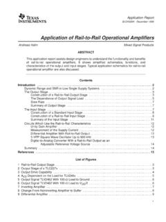
5 Such an amplifier is called a*differential amplifier (DA).A differential amplifier is a circuit that can accept two input signals and amplify thedifference between these two input shows the block diagram of an ordinary amplifier . The input voltage v is amplifiedto Av where A is the voltage gain of the amplifier . Therefore, the ouput voltage is v0 = Av. Fig. shows the block diagram of a differential amplifier . There are two input voltages v1and v2. This amplifier amplifies the difference between the two input voltages. Therefore, the outputvoltage is v0 = A(v1 v2) where A is the voltage gain of the A differential amplifier has an open-circuit voltage gain of 100. The inputsignals are V and Determine the output voltage, v0=A(v1 v2)Here,A = 100 ; v1= V : v2 = v0= 100( ) = Basic Circuit of Differential AmplifierFig.
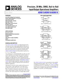
6 (i) shows the basic circuit of a differential amplifier . It consists of two transistors Q1and Q2 that have identical (ideally) characteristics. They share a common positive supply **VCC,common emitter resistor RE and common negative supply VEE. Note that the circuit is (ii) shows the symbol of differential following points may be noted about the differential amplifier :(i)The differential amplifier (DA) is a two-input terminal device using atleast two are two output terminals marked 1 (vout 1) and 2(vout 2). *The name is appropriate because the amplifier is amplifying the difference between thetwo input Amplifiers 665*The operation of double-ended input DA will then be easier to understand.(ii)The DA transistors Q1 and Q2 are matched so that their characteristics are the same.
7 Thecollector resistors (RC1 and RC2) are also equal. The equality of the matched circuitcomponents makes the DA circuit arrangement completely symmetrical.(iii)We can apply signal to a differential amplifier (DA) in the following two ways :(a)The signal is applied to one input of DA and the other input is grounded. In that case,it is called single-ended input arrangement.(b)The signals are applied to both inputs of DA. In that case, it is called dual-ended ordouble-ended input arrangement.(iv)We can take output from DA in the following two ways :(a)The output can be taken from one of the output terminals and the ground. In that case,it is called single-ended output arrangement.(b)The output can be taken between the two output terminals ( , between the collectorsof Q1 and Q2). In that case, it is called double-ended output arrangement ordifferential output.
8 (v)Generally, the differential amplifier (DA) is operated for single-ended output. In otherwords, we take the output either from output terminal 1 and ground or from outputterminal 2 and ground. Any input/output terminal that is grounded is at Operation of Differential AmplifierFor *simplicity, we shall discuss the operation of single-ended input ( , signal is applied to oneinput of DA and the other input is grounded) and double-ended output DA.(i)Suppose the signal is applied to input 1 ( , base of transistor Q1) and input 2 ( , baseof transistor Q2) is grounded as shown in Fig. The transistor Q1 will act in two ways : as acommon emitter amplifier and as a common collector amplifier . As a common emitter amplifier , theinput signal to Q1 (input 1) will appear at output 1 ( , collector of Q1) as amplified inverted signalas shown in Fig.
9 As a common collector amplifier , the signal appears on the emitter of Q1 inphase with the input and only slightly smaller. Since the emitters of Q1 and Q2 are common, the (i)(ii)Fig. Principles of Electronicsemitter signal becomes input to Q2. Therefore, Q2 functions as a *common base amplifier . As a result,the signal on the emitter of Q2 will be amplified and appears on output 2 ( , collector of Q2) in phasewith the emitter signal and hence in phase with the input signal (signal at input 1). This is illustratedin Fig. (ii)Now suppose the signal is applied to input 2( , base of transistor Q2) and input 1(base oftransistor Q1) is grounded. As explained above, now Q2 acts as a common emitter amplifier andcommon collector amplifier while Q1 functions as a common base amplifier .
10 Therefore, an invertedand amplified signal appears at output 2 ( , at collector of Q2) and non-inverted, amplified signalappears at output 1( , at collector of Q1). This is illustrated in Fig. following points are worth noting about single-ended input DA :(a)When signal is applied to input 1 ( , base of transistor Q1 in Fig. ), an inverted,amplified signal appears at output 1 and non-inverted, amplified signal appears at output2. Reverse happens when signal is applied to input 2 and input 1 is grounded. *In a common base amplifier , output signal is in phase with the input signal. Recall that only in CEamplifier, the output voltage is 180 out of phase with the input voltage. operational Amplifiers 667(b)When only one output terminal is available, the phase of the output of single-ended inputDA depends on which input receives the input signal.