Transcription of 8-bit Arithmetic Logic Unit Design Report
1 8-bit Arithmetic Logic unit Design Report Fang, Hongxia Zhang, Zhaobo Zhao, Yang Zhong, Wei Instructor: James Morizio 2007-12-09 ECE 261 Project8bit ALU Design ReportOutline - Generalization - Function - Structure - Assignment - Design results - Summary GeneralizationALU ( Arithmetic Logic unit ) A critical component of the microprocessor, the core component of central processing unit . ALU comprises the combinational Logic that implements Logic operations such as AND and OR, and Arithmetic operations such as Addition, Subtraction, and Multiplication.
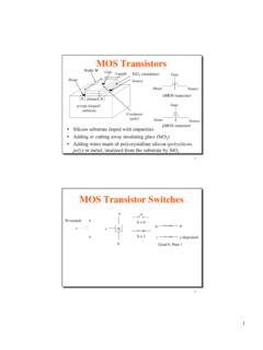
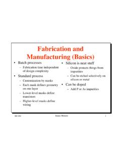
2 GeneralizationA and B: N-bit InputsResult: N-bit OutputOp: ALU operation, K-bit means could support maximum 2k operationZero, CarryOut, Overflow: 1-bit flagABNNNR esultKOpCarryOutZeroOverflowALUALU symbolFunction8 Functions Logic : And; Or; Inv SHIFT: signed-shift left signed-shift right ALOGRITHM: Add Subtract Multiply3 bit control signals To choose the functionStructureSchematic 7 componentsStructureLayout - placeAssignment Logic & Control Wei Zhong Shift Yang Zhao Add & Subtract Hongxia Fang Multiply Zhaobo ZhangEveryone is in charge of each part's schematic simulation and layout verificationDesign results8 to 1 MUX - Using compound gate to realize 2 to 1 MUX YDSDS=+8 to 1 MuxSet A0=1, A1~A7=0.
3 WhenS2S1S0=000, Out=18-bit 8 to 1 MuxLayout of 1-bit Mux81 2-bit Mux81 Logic Function8-bit ANDS imulation for 8bit input AND Input A[7:0]=01010101, B[7:0]=10101010, Q[7:0]=00000000 8bit ORLogic FunctionSimulation for 8bit input OR Input A[7:0]=01010101, B[7:0]=10101010, Q[7:0]=11111111 Simulation for 8bit input AND & ORLogic Function8bit InvertorSimulation for 8bit input OR Input A[7:0]=01010101, Q[7:0]=10101010 Signed-Shift Right SchematicSimulation for Signed-shift right S0S1S2=010, connect A0 to extra bit, shift A7~A0=00101011 right for 2 bits, the output R7~R0=11001010 Signed-shift rightLayout consist of 24 2-input MUX, using Metal 1 and Metal 2 interconnects Signed-shift left SchematicSimulation for Signed-shift left S0S1S2=010, connect A7 to extra bit, shift A7~A0=00101011 left for 2 bits, the output R7~R0=10101100 Signed-shift leftLayout consist of 24 2-input MUX.
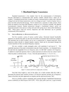
4 Using Metal 1 and Metal 2 interconnects 278-bit ripple Adder schematic288-bit ripple Add-sub schematic29 Simulation301-bit full adder layout 318-bit ripple adder layout (part)328-bit add-sub layout (part)4-bit Booth MultiplierSchematic4-bit Booth MultiplierSimulationB*A=2*3 Multiplier A ---0000 0011 Multiplicand B ---0010 0000 Stage1: 0000 00110 subtract B, shift - 0010 0000 Stage2: 1111 00011 nothing, shiftStage3: 1111 10001 add B, shift + 0010 0000 Stage4: 0000 11000 nothing, shiftProduct:0000 0110-----done, 6=2*34-bit Booth MultiplierStage1 out-11110001 stage2 out-11111000 Stage3 out-00001100 stage4 out-000001104-bit Booth MultiplierLayoutSummaryWe successfully Design 8-bit ALU, supporting 4-bit multiplication.
5 The Design has a right simulation result and passes the DRC and LVS verificationFinal chip: 4464 transistors S=2mm*2mm