Transcription of Boundary Scan Tutorial - All Faculty
1 Boundary scan Tutorial 1 Boundary scan Tutorial A Tutorial prepared by Dr R G Ben Bennetts DFT Consultant and Director, ASSET InterTech Inc. Tel: +44 1489 581276 E-mail: Figure 1 Welcome!! Boundary - ScanTut or ia lBoundary- ScanTut or ia lA Tutorial prepared by Dr R G Ben BennettsDFT Consult ant , Direct or, ASSET Int erTech Inc. +44 1489 581276be n @d f t . c o . u f t . c o. u kA Tutorial prepared by Dr R G Ben BennettsDFT Consult ant , Direct or, ASSET Int erTech Inc. +44 1489 581276ben@dft .. Version 25 September, 2002 Boundary scan Tutorial 2 Introduction and Objectives Figure 2 IEEE Standard Boundary - scan Standard In this Tutorial , you will learn the basic elements of Boundary - scan architecture where it came from, what problem it solves, and the implications on the design of an integrated-circuit device.
2 The core reference is the IEEE Standard: IEEE Standard Test Access Port and Boundary - scan Architecture, available from the IEEE, 445 Hoes Lane, PO Box 1331, Piscataway, New Jersey 08855-1331, USA. The standard was first published in 1990, revised in 1993 and 1994, and most recently in 2001. You can obtain a copy of the Standard via the world wide web on the IEEE home page at: The 1993 revision to the standard, referred to as , contained many clarifications, corrections, and minor enhancements. Two new instructions were introduced in and these are described in this Tutorial .
3 The supplement contained a description of the Boundary - scan Description Language (BSDL). The version contains enhancements to the wording, plus removal of the use of the all-0s code for the Extest instruction. In addition, the mandatory Sample/Preload instruction has been spit into two separate instructions: Preload and Sample, both still mandatory. Version 25 September, 2002 Boundary scan Tutorial 3 For further, more recent publications on Boundary - scan topics, see the To Probe Further section at the end of this Tutorial .
4 Course Pre-Requisites Figure 3 Course Pre-RequisitesYou will need to know the basics of logic design plus have a general understanding of Integrated Circuit design and Printed-Circuit Board design, assembly and test Students who participate in this course are expected to know the basics of logic design plus have a general understanding of Integrated Circuit design principles and Printed-Circuit Board electronic design, board assembly and test techniques. Version 25 September, 2002 Boundary scan Tutorial 4 About The Author Figure 4 About The AuthorDr R G Ben Bennetts is an independent consultant in Design-For-Test (DFT), consulting in product life-cycle DFT strategies, and delivering on-site and open educational courses in DFT technologies.
5 Previously, he has worked for LogicVision, Synopsys, GenRad and Cirrus Computers. Between 1986 and 1993, he was a free-lance consultant and lecturer on Design-for-Test (DFT) topics. During this time, he was a member of JTAG, the organization that created the IEEE Boundary - scan Standard. He is an Advisory member of the Board of Directors of ASSET InterTechBen has published over 90 papers plus three books on test and DFT subjects. Dr R G Ben Bennetts is an independent consultant in Design-For-Test (DFT), consulting in product life-cycle DFT strategies, and delivering on-site and open educational courses in DFT technologies.
6 Previously, he has worked for LogicVision, Synopsys, GenRad and Cirrus Computers. Between 1986 and 1993, he was a free-lance consultant and lecturer on Design-for-Test (DFT) topics. During this time, he was a member of JTAG, the organization that created the IEEE Boundary - scan Standard. He is an Advisory member of the Board of Directors of ASSET InterTech. Ben has published over 90 papers plus three books on test and DFT subjects. Version 25 September, 2002 Boundary scan Tutorial 5 The Motivation for Boundary - scan Architecture Historical Development: In-Circuit Test Figure 5 Bed-Of-Nails (MDA, ICT)In-Circuit & Functional Board TestFunctional Since the mid-1970s, the structural testing of loaded printed circuit boards has relied very heavily on the use of the so-called in-circuit bed-of-nails technique (see Figure 5).
7 This method of testing makes use of a fixture containing a bed-of-nails to access individual devices on the board through test lands laid into the copper interconnect, or into other convenient physical contact points. Testing then proceeds in two phases: power-off tests followed by power-on tests. Power-off tests check the integrity of the physical contact between nail and the on-board access point, followed by open and shorts tests based on impedance measurements. Power-on tests apply stimulus to a chosen device, or collection of devices (known as a cluster), with an accompanying measurement of the response from that device or cluster.
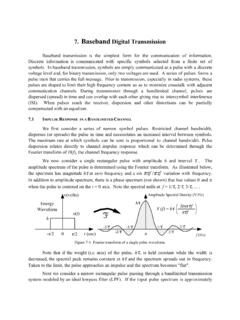
8 Other devices that are electrically connected to the device-under-test are usually placed into a safe state (a process called guarding ). In this way, the tester is able to check the presence, orientation, and bonding of the device-under-test in place on the board. Version 25 September, 2002 Boundary scan Tutorial 6 Changes in Device Packaging Styles Figure 6 Change of Device Packaging StylesDIPPGASOICTSOPSOJPLCCQFPBGA Fundamentally, the in-circuit bed-of-nails technique relied on physical access to all devices on a board.
9 For plated-through-hole technology, the access is usually gained by adding test lands into the interconnects on the B side of the board that is, the solder side of the board. The advent of onserted devices packaged in surface mount styles see Figure 6 - meant that system manufacturers began to place components on both sides of the board the A side and the B side. The smaller pitch between the leads of surface-mount components caused a corresponding decrease in the physical distance between the interconnects.
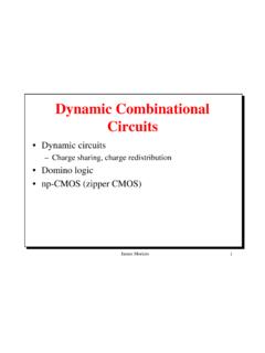
10 Version 25 September, 2002 Boundary scan Tutorial 7 Probing Multi-Layer Boards Figure 7 Probing Multi-Layer Boards The move to surface-mount packaging had a serious impact on the ability to place a nail accurately onto a target test land, as shown in Figure 7. The whole question of access was further compounded by the development of multi-layer boards created to accommodate the increased number of interconnects between all the devices.