Search results with tag "Impulse response"
Time Response of Second Order Systems - Mercer University
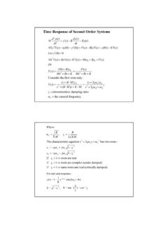
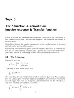
faculty.mercer.eduImpulse response of the second order system: Laplace transform of the unit impulse is R(s)=1 Impulse response: Transient response for the impulse function, which is simply is the derivative of the response to the unit step: ( 2) 2 2 2 n n n s s Y s ζω ω ω + + = y(t) e sin(n t)n n t ω β β = ω −ζω Responses and pole locations Time Responses and Pole Locations:

5.9 Frequency Response of the Common-Emitter Amp
www.ittc.ku.edu“implies” that the impulse response of the amplifier is: gt( )=−200δ(t) Are you saying the impulse response of the common-emitter example is not this function? A: It is definitely not that function. The impulse response gt( )=−200δ(t) is ideal—the impulse response of an amplifier with an infinite bandwidth!
Topic 3 The -function & convolution. Impulse response ...
www.robots.ox.ac.ukIn the time domain, a system is described by its Impulse Response Function h(t). This function literally describes the response of system at time tto an unit impulse or -function input administered at time t= 0. Suppose that \now" is time t, and you administered an impulse to the system at time ˝in the past. The response now is y(t) = h(t ...

Convolution solutions (Sect. 6.6). Convolution of two ...
users.math.msu.eduI Impulse response solution. I Solution decomposition theorem. Impulse response solution. Definition The impulse response solution is the function y δ solution of the IVP y00 δ + a 1 y 0 δ + a 0 y δ = δ(t − c), y δ(0) = 0, y δ 0(0) = 0, c ∈ R. Example Find the impulse response solution of the IVP y00 δ +2 y 0 δ +2 y δ = δ(t − ...

Convolution solutions (Sect. 4.5). - Michigan State University
users.math.msu.eduSummary: The impulse reponse solution is the inverse Laplace Transform of the reciprocal of the equation characteristic polynomial. Impulse response solution. Recall: The impulse response solution is y δ solution of the IVP y00 δ + a 1 y 0 δ + a 0 y δ = δ(t), y δ(0) = 0, y δ 0(0) = 0. Example Find the solution (impulse response at t = c ...

The Scientist and Engineer's Guide to Digital Signal ...
www.analog.comof this characteristic, recursive filters are also called Infinite Impulse Response or IIR filters. In comparison, filters carried out by convolution are called Finite Impulse Response or FIR filters. As you know, the impulse response is the output of a system when the input is
Transfer Functions, Poles and Zeros - Waterloo Maple
www.maplesoft.comThe step response of the transfer function can be written as This can be expanded to get The first term on the RHS is an impulse response and second term is a step response. Unit impulse response plots for some different cases This subsection contains some more plots that show the effect of pole locations and help illustrate the general trends.

SECTION 6 DIGITAL FILTERS - Analog Devices
www.analog.cominfinite impulse response (IIR). As the terminology suggests, these classifications refer to the filter’s impulse response. By varying the weight of the coefficients and the number of filter taps, virtually any frequency response characteristic can be realized with an FIR filter. As has been shown, FIR filters can achieve performance

Teaching Notes on Impulse Response Function and …
faculty.ndhu.edu.tw• VAR/View/Impulse/Eviews • FinMetrics/Splus 2. Cointegration: • CATS/RATS • COINT2/GAUSS • VAR/Eviews • urca/R • FinMetrics/Splus 3. Impulse response under cointegration constraint: CATS,CATSIRFS/RATS References 1. Lutkepohl, Helmut Introduction to multiple time series analysis, 2nd ed. Springer-Verlag, 1991. 2.
Chapter 2 Linear Time-Invariant Systems
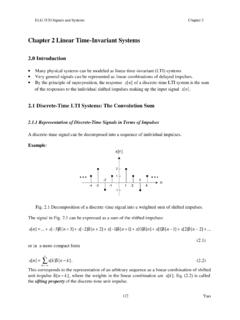
www.site.uottawa.ca2.1.2 Discrete-Time Unit Impulse Response and the Convolution – Sum Representation of LTI Systems Let h k [n] be the response of the LTI system to the shifted unit impulse d[n − k], then from the superposition property for a linear system, the response of …
Lecture 3 ELE 301: Signals and Systems - Princeton University
www.princeton.eduImpulse Response The impulse response of a linear system h ˝(t) is the output of the system at time t to an impulse at time ˝. This can be written as h ˝= H( ˝) Care is required in interpreting this expression! H 0 t! h(t,0) h(t,!)!(t! ")!(t) t Cu (Lecture 3) ELE 301: Signals and Systems Fall 2011-12 3 / 55 Note: Be aware of potential ...

5Properties of Linear, Time-Invariant Systems
ocw.mit.eduvertible, then the impulse response hi of the inverse system has the property that h convolved with hi is an impulse. For LTI systems an equivalent condi-tion to stability is that the impulse response be absolutely summable (discrete time) or absolutely integrable (continuous time). If an LTI system is causal,

Chapter 4: Problem Solutions
faculty.nps.eduthe impulse response of a FIR filter which approximates this frequency response. Plot the frequency response in terms of magnitude and phase to verify that the approximation holds. Solution In the digital domain, let 2 F Fs and therefore F Fs 2 . Therefore the filter's desired frequency response becomes H
CHAPTER 8 ANALOG FILTERS
www.analog.comIMPULSE RESPONSE 8.19 STEP RESPONSE 8.20 SECTION 8.4: STANDARD RESPONSES 8.21 BUTTERWORTH 8.21 CHEBYSHEV 8.21 BESSEL 8.23 ... dependent change in the input/output transfer function that is defined as the frequency response. Filters have many practical applications. A simple, single-pole, low-pass filter (the
SECTION 6 DIGITAL FILTERS - Mixed-signal and digital ...
www.analog.comDIGITAL FILTERS 6.a SECTION 6 DIGITAL FILTERS Finite Impulse Response (FIR) Filters Infinite Impulse Response (IIR) Filters Multirate Filters Adaptive Filters

Understanding Digital Signal Processing - …
ptgmedia.pearsoncmg.com5.10 Analyzing FIR Filters 226 References 235 Chapter 5 Problems 238 6 INFINITE IMPULSE RESPONSE FILTERS 253 6.1 An Introduction to Infinite Impulse Response …

Transfer Function Models of Dynamical Processes
chemeng.queensu.caTransfer function is the unit impulse response e.g. First order process, Unit impulse response is given by In the time domain, 10 Transfer Function

Nyquist Sampling Theorem - Illinois Institute of Technology
web.iit.edu• Impulse Response Train • Fourier Transform of Impulse Response Train • Sampling in the Fourier Domain o Sampling cases • Review . What is the Nyquist Sampling Theorem? • Formal Definition: o If the frequency spectra of a function x(t) contains no frequencies higher than B hertz, x(t) is completely determined by giving its

Lecture 11: Discrete-time Fourier transform
ocw.mit.eduier transform, the discrete-time Fourier transform is a complex-valued func-tion whether or not the sequence is real-valued. Furthermore, as we stressed in Lecture 10, the discrete-time Fourier transform is always a periodic func- ... Impulse response and frequency response for a first-order system approximating a lowpass filter and a first ...
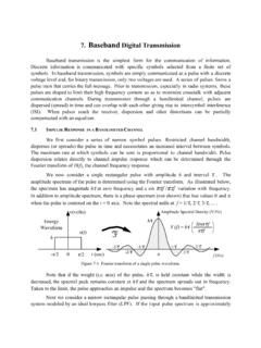
7. Baseband Digital Transmission
people.ee.duke.eduAdditionally, an ideal filter must have an impulse response that extends to infinite time before and after the pulse peak and, if the filter is to be causal (output response occurs after the input is applied), the peak output would occur an infinite time after the input. This would

Lecture 7a: Vector Autoregression (VAR)
www.fsb.miamioh.eduThe goal of structural VAR analysis is to obtain B, which is not unique (for a bivariate system Ω has 3 unique elements, while B has 4 elements to be determined). 3. The Sims (1980) structural VAR imposes the restriction that B ... Instead, we simulate the impulse response for VAR(p) 28.

제12장 VAR과VECM - elearning.kocw.net
elearning.kocw.net벡터자기회귀(VAR) 모형 §충격반응함수(impulse response function) • 충격반응함수는VAR의추정계수를바탕으로모형내의어 떤변수에 ...

Root Raised Cosine (RRC) Filters and Pulse Shaping in ...
ntrs.nasa.govImpulse response now has a sinc term that ensures that it has zero crossings as like ideal low pass filter. 5/7/2012 8 ... RRC theoretically has infinite number of taps so it has infinite attenuation in the stop band. However, in implementation its length …

Simulation Study of FIR Filter based on MATLAB - …
www.ijsrd.comC. only need to move the module of module library to window Window function design steps of FIR filter: 1) The unit impulse response hd(n)of ideal filter was

3F3 5 Design of FIR Filters - Vyssotski
www.vyssotski.ch69 FIR as a class of LTI Filters Transfer function of the filter is Finite Impulse Response (FIR) Filters: N = 0, no feedback

EL 713: Digital Signal Processing Extra Problem Solutions
eeweb.engineering.nyu.eduThe DTFT of a rectangular pulse is a digital sinc function, so the DFT of a rectangular pulse is samples of the sinc function. So signal 8 corresponds to DFT 5. That leaves signal 5 and DFT 8. Signal 5 can be written as a cosine times a rectangular pulse, so the ... IMPULSE RESPONSE-1 0 1-1-0.5 0 0.5 1 5 Real Part Imaginary Part ZEROS OF H(z)

Impulse Response and Convolution
sigproc.mit.eduImpulse Response A CT system is completely characterized by its impulse response, much as a DT system is completely characterized by its unit-sample response. We have worked with the impulse (Dirac delta) function δ(t) previously. It’s de ned in a limit as follows. Let p ∆(t) represent a pulse of width ∆ and height 1 ∆ so that its area ...
Similar queries
Response, Impulse response, Impulse, Infinite, Function, Impulse Response Function, Infinite impulse response, Analog Devices, Eviews, Princeton University, DIGITAL, Understanding Digital Signal Processing, 11: Discrete-time Fourier transform, Discrete-time Fourier transform, Func, Tion, Structural VAR, Raised Cosine, Simulation Study of FIR Filter, 5 Design of FIR Filters