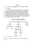
Transcription of 93AA46A/B/C, 93LC46A/B/C, 93C46A/B/C
1 2002-2013 Microchip Technology 193AA46A/B/C, 93LC46A/B/C, 93C46A/B/CDevice Selection TableFeatures: Low-Power CMOS Technology ORG Pin to Select Word Size for 46C Version 128 x 8-bit Organization A Devices (no ORG) 64 x 16-bit Organization B Devices (no ORG) Self-Timed Erase/Write Cycles (including Auto-Erase) Automatic Erase All (ERAL) Before Write All (WRAL) Power-On/Off Data Protection Circuitry Industry Standard 3-Wire Serial I/O Device Status Signal (Ready/Busy) Sequential Read Function 1,000,000 Erase/Write Cycles Data Retention > 200 Years RoHS Compliant Temperature Ranges Supported:Pin Function TableDescription:The Microchip Technology Inc. 93XX46A/B/C devicesare 1 Kbit low-voltage serial Electrically ErasablePROMs (EEPROM). Word-selectable devices such asthe 93AA46C, 93LC46C or 93C46C are dependentupon external logic levels driving the ORG pin to setword size.
2 For dedicated 8-bit communication, the93AA46A, 93LC46A or 93C46A devices are available,while the 93AA46B, 93LC46B and 93C46B devicesprovide dedicated 16-bit communication. AdvancedCMOS technology makes these devices ideal for low-power, nonvolatile memory applications. The entire93XX Series is available in standard packages includ-ing 8-lead PDIP and SOIC, and advanced packagingincluding 8-lead MSOP, 6-lead SOT-23, 8-lead2x3 DFN/TDFN and 8-lead TSSOP. All packages arePb-free (Matte Tin) NumberVCC RangeORG PinWord SizeTemp , SN, ST, MS, OT, MC, , SN, ST, MS, OT, MC, , EP, SN, ST, MS, OT, MC, , EP, SN, ST, MS, OT, MC, , EP, SN, ST, MS, OT, MC, , EP, SN, ST, MS, OT, MC, or 16-bitIP, SN, ST, MS, MC, or 16-bitI, EP, SN, ST, MS, MC, or 16-bitI, EP, SN, ST, MS, MC, MN- Industrial (I)-40 C to +85 C- Automotive (E) -40 C to +125 CNameFunctionCSChip SelectCLKS erial Data ClockDISerial Data InputDOSerial Data OutputVSSG roundNCNo internal connectionORGM emory ConfigurationVCCP ower Supply1K Microwire Compatible Serial EEPROM93AA46A/B/C, 93LC46A/B/C, 93C46A/B/CDS20001749K-page 2 2002-2013 Microchip Technology Types (not to scale)CSCLKDIDO12348765 VCCNCORG*VSSPDIP/SOIC(P, SN)CSCLKDIDO12348765 VCCNCORG*VSSROTATED SOIC(ex.)
3 93LC46BX)TSSOP/MSOPCSCLKDIDO12348765 VCCNCORG*VSS(ST, MS)SOT-23 DOVSSDI123654 VCCCSCLK(OT)*ORG pin is NC on A/B devicesDFN/TDFNCSCLKDIDONCORG*VSSVCC8765 1234(MC, MN) 2002-2013 Microchip Technology 393AA46A/B/C, 93LC46A/B/C, 93C46A/ CHARACTERISTICSA bsolute Maximum Ratings( ) inputs and outputs to VCC + temperature .. -65 C to +150 CAmbient temperature with power C to +125 CESD protection on all pins 4kVTABLE 1-1:DC CHARACTERISTICS NOTICE: Stresses above those listed under Absolute Maximum Ratings may cause permanent damage tothe device. This is a stress rating only and functional operation of the device at those or any other conditionsabove those indicated in the operational listings of this specification is not implied. Exposure to maximum ratingconditions for extended periods may affect device parameters apply over the specified ranges unless otherwise (I):TA = -40 C to +85 C, VCC = + TO + (E).
4 TA = -40 C to +125 C, VCC = + TO + input VCC VCC +1 VCC +1 VVVCC input VCCVVVCC output voltage = mA, VCC = = 100 A, VCC = output - VVIOH = -400 A, VCC = IOH = -100 A, VCC = leakage current 1 AVIN = VSS or VCCD6 ILOO utput leakage current 1 AVOUT = VSS or VCCD7 CIN,COUTPin capacitance(all inputs/outputs) 7pFVIN/VOUT = 0V (Note 1)TA = 25 C, FCLK = 1 MHzD8 ICC writeWrite current 5002 mA AFCLK = 3 MHz, VCC = = 2 MHz, VCC = read Read current 1001500 mA A AFCLK = 3 MHz, VCC = = 2 MHz, VCC = = 2 MHz, VCC = current 15 A AI-TempE-TempCLK = CS = 0 VORG = DI = VSS or VCC (Note 2) (Note 3)D11 VPORVCC voltage detect VV(Note 1)93AA46A/B/C, 93LC46A/B/C93C46A/B/CNote 1:This parameter is periodically sampled and not 100% :ORG pin not available on A or B :Ready/Busy status must be cleared from DO; see Section Data Out (DO).
5 93AA46A/B/C, 93LC46A/B/C, 93C46A/B/CDS20001749K-page 4 2002-2013 Microchip Technology 1-2:AC CHARACTERISTICSAll parameters apply over the specified ranges unless otherwise (I):TA = -40 C to +85 C, VCC = + TO + (E): TA = -40 C to +125 C, VCC = + TO + frequency VCC , 93XX46C VCC VCC high time200250450 VCC , 93XX46C VCC VCC low time100200450 VCC , 93XX46C VCC VCC Select setup time50100250 VCC VCC VCC Select hold time0 VCC Select low time250 VCC input setup time50100250 VCC , 93XX46C VCC VCC input hold time50100250 VCC , 93XX46C VCC VCC output delay time VCC , CL = 100 VCC , CL = 100 VCC , CL = 100 pFA10 TCZData output disable time VCC , (Note 1) VCC , (Note 1)A11 TSVS tatus valid time VCC , CL = 100 VCC , CL = 100 VCC , CL = 100 pFA12 TWCP rogram cycle time 6msErase/Write mode (AA and LC versions)A13 TWC 2msErase/Write mode (93C versions)
6 A14 TEC 6msERAL mode, VCC 15msWRAL mode, VCC Endurance1M cycles 25 C, VCC = , (Note 2)Note 1:This parameter is periodically sampled and not 100% :This application is not tested but ensured by characterization. For endurance estimates in a specificapplication, please consult the Total Endurance Model, which may be obtained from Microchip s website at 2002-2013 Microchip Technology 593AA46A/B/C, 93LC46A/B/C, 93C46A/B/CFIGURE 1-1:SYNCHRONOUS DATA TIMINGTABLE 1-3: INSTRUCTION SET FOR X16 ORGANIZATION (93XX46B OR 93XX46C WITH ORG = 1)TABLE 1-4: INSTRUCTION SET FOR X8 ORGANIZATION (93XX46A OR 93XX46C WITH ORG = 0)InstructionSBOpcodeAddressData In Data OutReq. CLK CyclesERASE111A5A4A3A2A1A0 (RDY/BSY)9 ERAL1001 0 XXXX (RDY/BSY)9 EWDS1000 0 XXXX High-Z9 EWEN1001 1 XXXX High-Z9 READ110A5A4A3A2A1A0 D15 - D025 WRITE101A5A4A3A2A1A0D15 - D0(RDY/BSY)25 WRAL1000 1 XXXXD15 - D0(RDY/BSY)25 InstructionSBOpcodeAddressData In Data OutReq.
7 CLK CyclesERASE111A6 A5 A4 A3 A2 A1 A0 (RDY/BSY)10 ERAL1001 0 XXXXX (RDY/BSY)10 EWDS1000 0 XXXXX High-Z10 EWEN1001 1 XXXXX High-Z10 READ110A6 A5 A4 A3 A2 A1 A0 D7 - D018 WRITE101A6 A5 A4 A3 A2 A1 A0D7 - D0(RDY/BSY)18 WRAL1000 1 XXXXXD7 - D0(RDY/BSY)18 CSVIHVILVIHVILVIHVILVOHVOLVOHVOLCLKDIDO( Read)DO(Program)TCSSTDISTCKHTCKLTDIHTPDT CSHTPDTCZS tatus ValidTSVTCZNote:TSV is relative to , 93LC46A/B/C, 93C46A/B/CDS20001749K-page 6 2002-2013 Microchip Technology DESCRIPTIONWhen the ORG pin (93XX46C) is connected to VCC,the (x16) organization is selected. When it is connectedto ground, the (x8) organization is selected. Instruc-tions, addresses and write data are clocked into the DIpin on the rising edge of the clock (CLK). The DO pin isnormally held in a High-Z state except when readingdata from the device, or when checking the Ready/Busy status during a programming operation.
8 TheReady/Busy status can be verified during an erase/write operation by polling the DO pin; DO low indicatesthat programming is still in progress, while DO highindicates the device is ready. DO will enter the High-Zstate on the falling edge of ConditionThe Start bit is detected by the device if CS and DI areboth high with respect to the positive edge of CLK forthe first a Start condition is detected, CS, CLK and DImay change in any combination (except to that of aStart condition), without resulting in any deviceoperation (Read, Write, Erase, EWEN, EWDS, ERALor WRAL). As soon as CS is high, the device is nolonger in Standby instruction following a Start condition will only beexecuted if the required opcode, address and data bitsfor any particular instruction are clocked In/Data Out (DI/DO)It is possible to connect the Data In and Data Out pinstogether.
9 However, with this configuration it is possiblefor a bus conflict to occur during the dummy zero that precedes the read operation if A0 is a logic highlevel. Under such a condition the voltage level seen atData Out is undefined and will depend upon the relativeimpedances of Data Out and the signal source drivingA0. The higher the current sourcing capability of A0,the higher the voltage at the Data Out pin. In order tolimit this current, a resistor should be connectedbetween DI and ProtectionAll modes of operation are inhibited when VCC is belowa typical voltage of for 93AA and 93LC devicesor for 93C EWEN and EWDS commands give additionalprotection against accidentally programming duringnormal power-up, the device is automatically in theEWDS mode. Therefore, an EWEN instruction must beperformed before the initial ERASE or WRITE instruc-tion can be DiagramNote:When preparing to transmit an instruction,either the CLK or DI signal levels must beat a logic low as CS is toggled :For added protection, an EWDS commandshould be performed after every writeoperation and an external 10 k pull-down protection resistor should be addedto the CS RegisterModeDecodeLogicClockRegisterAddr essDecoderAddressCounterOutputBufferDODI ORG*CSCLKVCCVSS*ORG input is not available on A/B devices 2002-2013 Microchip Technology 793AA46A/B/C, 93LC46A/B/C, 93C46A/ ERASE instruction forces all data bits of thespecified address to the logical 1 state.
10 CS is broughtlow following the loading of the last address bit. Thisfalling edge of the CS pin initiates the self-timedprogramming cycle, except on 93C devices where therising edge of CLK before the last address bit initiatesthe write DO pin indicates the Ready/Busy status of thedevice if CS is brought high after a minimum of 250 nslow (TCSL). DO at logical 0 indicates that programmingis still in progress. DO at logical 1 indicates that theregister at the specified address has been erased andthe device is ready for another 2-1:ERASE TIMING FOR 93AA AND 93LC DEVICESFIGURE 2-2:ERASE TIMING FOR 93C DEVICESNote:After the Erase cycle is complete, issuinga Start bit and then taking CS low will clearthe Ready/Busy status from Status111 ANAN-1 AN-2 A0 TSVTCZBusyReadyHigh-ZTWCHigh-ZCSCLKDIDOT CSLC heck Status111 ANAN-1 AN-2 A0 TSVTCZBusyReadyHigh-ZTWCHigh-Z93AA46A/B/ C, 93LC46A/B/C, 93C46A/B/CDS20001749K-page 8 2002-2013 Microchip Technology All (ERAL)The Erase All (ERAL) instruction will erase the entirememory array to the logical 1 state.