Transcription of A six-band, HF Windom antenna - QSL.net
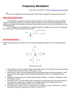
1 K3MT. presents .. A six- band , HF Windom antenna April, 1997. This Windom antenna was marketed in the late 70's and early 80's as Smithe's Windom . It was designed to cover 80, 40, 20 15, and 10 meters. By serendipity, it also covers the 17 and 2 meter bands. Now, how was a Windom antenna developed? It began with a center-fed, half-wave dipole. This antenna also works fairly well on all odd harmonics, because the center of the antenna has a current maximum, just as a half- wave antenna has. But on even harmonics, the center of the antenna has a current minimum. It is a high-impedance, center-fed Zepp antenna on even harmonics. This figure shows the current standing wave on a MHz half- wave dipole, and the currents on the second and third harmonics (7 and MHz.). When fed at the center - 90 degrees from one side - a good match to coax occurs on MHz. But the match at 7 MHz is bad: the current is a minimum, so the impedance is very high. So try feeding it 60 degrees from the left end.
2 Since the current at MHz is lower than at the center (and the voltage is higher) the feed impedance is higher - over 100 ohms. But the antenna is still resonant, so the reactance is low! What you have done is to increase its feed resistance. Look now at the action on 7 MHz. The feed point is no longer at a current minimum. Therefore, the second harmonic feed impedance is quite a bit lower than it had been earlier, and is in the range of a few hundred ohms. Since the antenna is resonant here, too, it has low reactance. But now the feed impedance at MHz is poor, because the 3rd harmonic current standing wave is now a minimum. So try feeding it at about 52. degrees from the left end. Here the match at , 7, and MHz is fairly good. The impedance at all three is now somewhere around 200 to 400. ohms. Now you can play these games all day, and if you build this antenna , you will find it works well on 80, 40, 20, 17, 15, 12, and 10 meters - plus 2. meters as well, provided you pay attention to the balun!
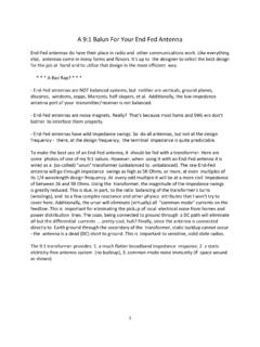
3 To boot, the balun matches 50 ohm coax without an antenna tuner. I admit, that this is a compromise design, and a tuner helps on the low end of 80 meters a bit, and on the high end of ten. But without a tuner, and with a fussy rig - my Drake TR-7 - a lot of DX has been worked on all bands, from 80 through 10. meters. I put my Windom up a bit differently, as shown here: Balun details What about the balun? The original unit sold with the Smithe Windoms is a Guanella-type (as opposed to a Ruthroff-Sevick design) parallel transmission line balun. Since the design impedance was measured to be between 300 and 600 ohms, a 9:1 down-converting balun with three 150. ohm lines was designed and built. To build one, obtain an Amidon T-250-2 core, tape it with two layers of black poly electrical tape, and obtain some #18 AWG magnet wire with a bit of #17 AWG teflon spaghetti. Twist the magnet wire to make three twisted pairs - about one twist per inch. Wind 11 turns of one pair on the core, and slip the teflon spaghetti over each lead of the remainder (untwist it a bit to do this.)
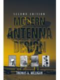
4 Then wind 8 more turns back overtop the 11 turn winding. Do this with the other two twisted pair lines as well. Space them on the core so no two lines overlap. This image shows a single winding on the core - make two more windings like it. Get an ohmmeter to check continuity. Label the lines A, B, and C, and their ends 1 & 2 where the uninsulated wire starts onto the core, and 3 & 4 where the wire (insulated with the spaghetti) leaves the winding. Pay attention to the wiring detail that follows, and use your ohmmeter to check your work. Label the wires so there is continuity from: A1 to A3. A2 to A4. B1 to B3. B2 to B4. C1 to C3. C2 to C4. Refer to the next image to guide the balun connections, and wire the balun as follows: Connect A1, B1, and C1 together. These will connect to the center conductor of the coax. Connect A2, B2, and C2 together. These must connect to the coax braid. Connect A3 to the short end of the Windom . This is important! Connect A4 to B3, and B4 to C3.
5 Connect C4 to a 110 pF, 6 kV capacitor. Connect the other end of this capacitor to the long end of the Windom . NOTE: if you think the balun is too complicated to build, e-mail us. We can provide one. Ask for pricing. In fact, we will be glad to provide an entire Windom , according to this design, if you wish. You are now ready to install and enjoy your Windom . If you have the same luck that K3MT and daughter KF4 LGR have, it will have been worth all the trouble! 73. K3MT. KF4 LGR.