Transcription of Adafruit HUZZAH32 - ESP32 Feather
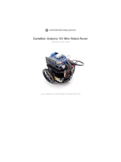
1 Adafruit HUZZAH32 - ESP32 FeatherCreated by lady ada updated on 2022-04-27 04:18:35 PM EDT Adafruit IndustriesPage 1 of 4336788891010141415151717181920212122222 324252626292932374141424243 Table of ContentsOverviewPinouts Power Pins Logic pins Serial pins I2C & SPI pins GPIO & Analog PinsAssembly Header Options! Soldering in Plain Headers Prepare the header strip: Add the breakout board: And Solder! Soldering on Female Header Tape In Place Flip & Tack Solder And Solder!Power Management Battery + USB Power Power supplies Measuring Battery ENable pin Alternative Power OptionsUsing with Arduino IDEW ipperSnapper Setup Sign up for Install WipperSnapperWipperSnapper Usage Blink a LED Read a Push-Button Read an I2C Sensor Going FurtherESP32 Files Schematic and Fabrication print Adafruit IndustriesPage 2 of 43 Overview Aww yeah, it's the Feather you have been waiting for!
2 The HUZZAH32 is our ESP32 -based Feather , made with the official WROOM32 module. We packed everything youlove about Feathers: built in USB-to-Serial converter, automatic bootloader reset,Lithium Ion/Polymer charger, and all the GPIO brought out so you can use it with anyof our Feather module nestled in at the end of this Feather contains a dual-core ESP32 chip, 4MB of SPI Flash, tuned antenna, and all the passives you need to take advantage ofthis powerful new processor. The ESP32 has both WiFi and Bluetooth Classic/LEsupport. That means it's perfect for just about any wireless or Internet-connectedproject. Adafruit IndustriesPage 3 of 43 Because it is part of our Feather eco-system you can take advantage of the 50+Wings ( ) that we've designed, to add all sorts of cool accessoriesThe ESP32 is a perfect upgrade from the ESP8266 that has been so popular. Incomparison, the ESP32 has way more GPIO, plenty of analog inputs, two analogoutputs, multiple extra peripherals (like a spare UART), two cores so you don't have toyield to the WiFi manager, much higher-speed processor, etc.
3 Etc! We think that as theESP32 gets traction, we'll see more people move to this chip exclusively, as it is sofull-featured. Adafruit IndustriesPage 4 of 43 Please note: The ESP32 is still targeted to developers. Not all of the peripherals arefully documented with example code, and there are some bugs still being found andfixed. We got all of our Featherwings working under Arduino IDE, so you can expectthings like I2C and SPI and analog reads to work. But other elements are still underdevelopment. For that reason, we recommend this Feather for makers who havesome experience with microcontroller programming, and not as a first dev are specifications from Espressif about the ESP32 ( )240 MHz dual core Tensilica LX6 microcontroller with 600 DMIPSI ntegrated 520 KB SRAMI ntegrated HT40 Wi-Fi transceiver, baseband, stack and LWIPI ntegrated dual mode Bluetooth (classic and BLE)4 MByte flashOn-board PCB antennaUltra-low noise analog amplifierHall sensor10x capacitive touch interface32 kHz crystal oscillator3 x UARTs (only two are configured by default in the Feather Arduino IDEsupport, one UART is used for bootloading/debug)3 x SPI (only one is configured by default in the Feather Arduino IDE support)2 x I2C (only one is configured by default in the Feather Arduino IDE support)
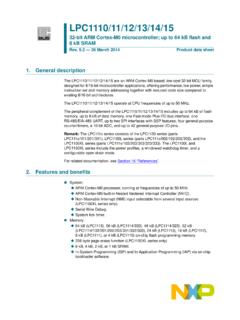
4 12 x ADC input channels2 x I2S Audio2 x DACPWM/timer input/output available on every GPIO pinOpenOCD debug interface with 32 kB TRAX bufferSDIO main/secondary 50 MHzSD-card interface support Adafruit IndustriesPage 5 of 43 Comes fully assembled and tested, with a USB interface that lets you quickly use itwith the Arduino IDE or the low-level ESP32 IDF. We also toss in some header so youcan solder it in and plug into a solderless breadboard. Lipoly battery and USB cable not included (but we do have lots of options in the shopif you'd like!)Pinouts Click here to view a PDF version of the pinout diagram ( )One of the great things about the ESP32 is that it has tons more GPIO than theESP8266. You won't have to juggle or multiplex your IO pins! There's a few things towatch out for so please read through the pinouts carefully Adafruit IndustriesPage 6 of 43 Power PinsGND - this is the common ground for all power and logicBAT - this is the positive voltage to/from the JST jack for the optional LipolybatteryUSB - this is the positive voltage to/from the micro USB jack if connectedEN - this is the regulator's enable pin.
5 It's pulled up, so connect to groundto disable the regulator3V - this is the output from the regulator. The regulator can supply 500mApeak but half of that is drawn by the ESP32 , and it's a fairly power-hungry chip. Adafruit IndustriesPage 7 of 43So if you need a ton of power for stuff like LEDs, motors, etc. Use the USB or BAT pins, and an additional regulatorLogic pinsThis is the general purpose I/O pin set for the microcontroller. All logic is pinsRX and TX are the additional Serial1 pins, and are not connected to the USB/Serialconverter. That means you can use them to connect to UART-devices like GPS's,fingerprint sensors, TX pin is the output from the module. The RX pin is the input into the are logicI2C & SPI pinsYou can use the ESP32 to control I2C and SPI devices, sensors, outputs, etc. If usingwith Arduino, the standard Wire and SPI devices work as you'd expect!
6 The ESP32 runs on power and logic, and unless otherwise specified, GPIO pins are not 5V safe! Adafruit IndustriesPage 8 of 43 Note that the I2C pins do not have pullup resistors already! You must add them if youwant to communicate with an I2C deviceGPIO & Analog PinsThere are tons of GPIO and analog inputs available to you for connecting LEDs,buttons, switches, sensors, etc. Here's the remaining pins row:A0 - this is an analog input A0 and also an analog output DAC2. It can also beused as a GPIO #26. It uses ADC #2A1 - this is an analog input A1 and also an analog output DAC1. It can also beused as a GPIO #25. It uses ADC #2A2 - this is an analog input A2 and also GPI #34. Note it is not an output-capablepin! It uses ADC #1 Adafruit IndustriesPage 9 of 43A3 - this is an analog input A3 and also GPI #39. Note it is not an output-capablepin! It uses ADC #1A4 - this is an analog input A4 and also GPI #36.
7 Note it is not an output-capablepin! It uses ADC #1A5 - this is an analog input A5 and also GPIO #4. It uses ADC #221 - General purpose IO pin #21 Top row:13 - This is GPIO #13 and also an analog input A12 on ADC #2. It's alsoconnected to the red LED next to the USB port12 - This is GPIO #12 and also an analog input A11 on ADC #2. This pin has apull-down resistor built into it, we recommend using it as an output only, ormaking sure that the pull-down is not affected during - This is GPIO #27 and also an analog input A10 on ADC #233 - This is GPIO #33 and also an analog input A9 on ADC #1. It can also beused to connect a 32 KHz - This is GPIO #15 and also an analog input A8 on ADC #232 - This is GPIO #32 and also an analog input A7 on ADC #1. It can also beused to connect a 32 KHz - This is GPIO #14 and also an analog input A6 on ADC #2 There's also an external analog inputA13 - This is general purpose input #35 and also an analog input A13, which is aresistor divider connected to the VBAT lineNote you can only read analog inputs on ADC #2 once WiFi has started as it is sharedwith the WiFi We ship Feathers fully tested but without headers attached - this gives you the mostflexibility on choosing how to use and configure your FeatherHeader Options!
8 Before you go gung-ho on soldering, there's a few options to consider! Adafruit IndustriesPage 10 of 43 The first option is soldering in plain maleheaders, this lets you plug in the Featherinto a solderless breadboard Adafruit IndustriesPage 11 of 43 Another option is to go with socket femaleheaders. This won't let you plug theFeather into a breadboard but it will letyou attach featherwings very easily Adafruit IndustriesPage 12 of 43 We also have 'slim' versions of the femaleheaders, that are a little shorter and give amore compact shape Adafruit IndustriesPage 13 of 43 Finally, there's the "Stacking Header"option. This one is sort of the best-of-both-worlds. You get the ability to plug into asolderless breadboard and plug afeatherwing on top. But its a little bulkySoldering in Plain Headers Prepare the header strip:Cut the strip to length if necessary. It willbe easier to solder if you insert it into abreadboard - long pins down Adafruit IndustriesPage 14 of 43 Add the breakout board:Place the breakout board over the pins sothat the short pins poke through thebreakout padsAnd Solder!
9 Be sure to solder all pins for reliableelectrical contact.(For tips on soldering, be sure to check outour Guide to Excellent Soldering ( )). Adafruit IndustriesPage 15 of 43 Solder the other strip as well. Adafruit IndustriesPage 16 of 43 You're done! Check your solder jointsvisually and continue onto the next stepsSoldering on Female Header Tape In PlaceFor sockets you'll want to tape them inplace so when you flip over the board theydon't fall out Adafruit IndustriesPage 17 of 43 Flip & Tack SolderAfter flipping over, solder one or twopoints on each strip, to 'tack' the header inplace Adafruit IndustriesPage 18 of 43 And Solder!Be sure to solder all pins for reliableelectrical contact.(For tips on soldering, be sure to check outour Guide to Excellent Soldering ( )). Adafruit IndustriesPage 19 of 43 You're done! Check your solder jointsvisually and continue onto the next stepsPower Management Adafruit IndustriesPage 20 of 43 Battery + USB PowerWe wanted to make the Feather HUZZAH32 easy to power both when connected to acomputer as well as via battery.
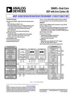
10 There's two ways to power a Feather . You canconnect with a Micro USB cable (just plug into the jack) and the Feather will regulatethe 5V USB down to You can also connect a Lithium Polymer (Lipo/Lipoly) or Lithium Ion (LiIon) battery to the JST jack. This will let the Feather run on arechargeable battery. When the USB power is powered, it will automatically switchover to USB for power, as well as start charging the battery (if attached) at 200mA. This happens 'hot-swap' style so you can always keep the LiPoly connected as a 'backup'power that will only get used when USB power is above shows the Micro USB jack (left), Lipoly JST jack (top left), as well as regulator (to the right of the JST jack), changeover diode+transistor (below theJST jack) and the Lipoly charging circuitry (right below the regulator).There's also a CHG LED next to the USB jack, which will light up while the battery ischarging.