Transcription of SRAM Technology - Electrical Engineering and Computer …
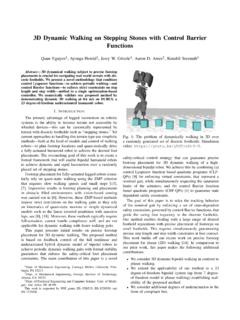
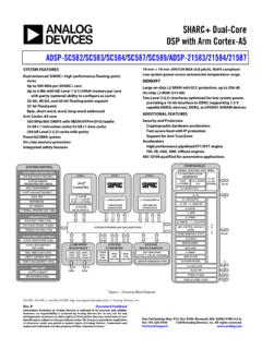
1 8 SRAM Technology . OVERVIEW. An SRAM ( static random access memory ) is designed to fill two needs: to provide a direct interface with the CPU at speeds not attainable by DRAMs and to replace DRAMs in systems that require very low power consumption. In the first role, the SRAM serves as cache memory , interfacing between DRAMs and the CPU. Figure 8-1 shows a typical PC microprocessor memory configuration. SRAM DRAM. External Cache (L2) Main memory 64KB to 1MB 4MB to 512MB. Microprocessor Internal Cache (L1). 8KB to 32KB. Source: Micron/ICE, " memory 1997" 20812.
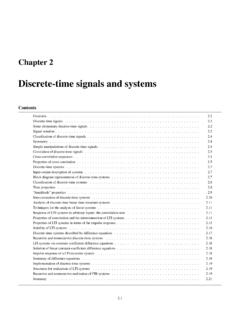
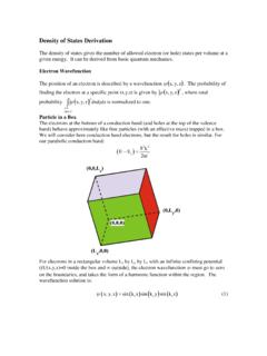
2 Figure 8-1. Typical PC Microprocessor memory Configuration The second driving force for SRAM Technology is low power applications. In this case, SRAMs are used in most portable equipment because the DRAM refresh current is several orders of mag- nitude more than the low-power SRAM standby current. For low-power SRAMs, access time is comparable to a standard DRAM. Figure 8-2 shows a partial list of Hitachi's SRAM products and gives an overview of some of the applications where these SRAMs are found. HOW THE DEVICE WORKS. The SRAM cell consists of a bi-stable flip-flop connected to the internal circuitry by two access transistors (Figure 8-3).
3 When the cell is not addressed, the two access transistors are closed and the data is kept to a stable state, latched within the flip-flop. INTEGRATED CIRCUIT Engineering CORPORATION 8-1. SRAM Technology 100 Industrial/Peripheral Buffer memory 64 Kbit Low-Power SRAM. 256 Kbit 1 Mbit 512K x 8. Low-Power SRAM Low-Power SRAM Low-Power SRAM. 50. Mass Storage Buffer memory 32K x 8 1M x 4/512K x 8. Asynchronous SRAM 128K x 8/64K x 16 Asynchronous SRAM. access Time (ns). 20. Asynchronous SRAM. 10 32K x 32/32K x 36. PC Cache memory Asynchronous SRAM. 256K x 18/128K x 36.
4 5 32K x 36 LVCMOS SSRAM. LVCMOS/HSTL SSRAM. Non PC Cache memory 2. 64 Kbit 256 Kbit 1 Mbit 4 Mbit Device Density Source: Hitachi/ICE, " memory 1997" 22607. Figure 8-2. Hitachi's SRAM Products Word Line B B. To Sense Amplifier Source: ICE, " memory 1997" 20019. Figure 8-3. SRAM Cell The flip-flop needs the power supply to keep the information. The data in an SRAM cell is volatile ( , the data is lost when the power is removed). However, the data does not leak away like in a DRAM, so the SRAM does not require a refresh cycle. 8-2 INTEGRATED CIRCUIT Engineering CORPORATION.
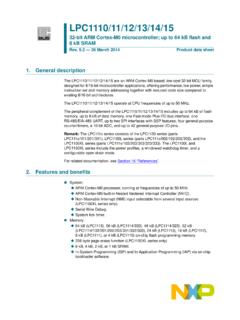
5 SRAM Technology Read/Write Figure 8-4 shows the read/write operations of an SRAM. To select a cell, the two access transis- tors must be on so the elementary cell (the flip-flop) can be connected to the internal SRAM cir- cuitry. These two access transistors of a cell are connected to the word line (also called row or X. address). The selected row will be set at VCC. The two flip-flop sides are thus connected to a pair of lines, B and B. The bit lines are also called columns or Y addresses. Word Line Word Line Column Decode Column Decode Sense Amplifier (Voltage Comparator).
6 Write Circuitry D Out D In READ OPERATION WRITE OPERATION. Source: ICE, " memory 1997" 19952. Figure 8-4. Read/Write Operations During a read operation these two bit lines are connected to the sense amplifier that recognizes if a logic data 1 or 0 is stored in the selected elementary cell. This sense amplifier then transfers the logic state to the output buffer which is connected to the output pad. There are as many sense amplifiers as there are output pads. During a write operation, data comes from the input pad. It then moves to the write circuitry.
7 Since the write circuitry drivers are stronger than the cell flip-flop transistors, the data will be forced onto the cell. When the read/write operation is completed, the word line (row) is set to 0V, the cell (flip-flop). either keeps its original data for a read cycle or stores the new data which was loaded during the write cycle. INTEGRATED CIRCUIT Engineering CORPORATION 8-3. SRAM Technology Data Retention To work properly and to ensure that the data in the elementary cell will not be altered, the SRAM. must be supplied by a VCC (power supply) that will not fluctuate beyond plus or minus five or ten percent of the VCC.
8 If the elementary cell is not disturbed, a lower voltage (2 volts) is acceptable to ensure that the cell will correctly keep the data. In that case, the SRAM is set to a retention mode where the power supply is lowered, and the part is no longer accessible. Figure 8-5 shows an example of how the VCC power supply must be lowered to ensure good data retention. ,,,, Data Retention Mode VDR 2V VCC. tCDR tR. ,,,, ,, , CE. Source: Cypress/ICE, " memory 1997" 22460. Figure 8-5. SRAM Data Retention Waveform memory CELL. Different types of SRAM cells are based on the type of load used in the elementary inverter of the flip-flop cell.
9 There are currently three types of SRAM memory cells : The 4T cell (four NMOS transistors plus two poly load resistors). The 6T cell (six transistors four NMOS transistors plus two PMOS transistors). The TFT cell (four NMOS transistors plus two loads called TFTs). 4 Transistor (4T ) Cell The most common SRAM cell consists of four NMOS transistors plus two poly-load resistors (Figure 8-6). This design is called the 4T cell SRAM. Two NMOS transistors are pass-transistors. These transistors have their gates tied to the word line and connect the cell to the columns.
10 The two other NMOS transistors are the pull-downs of the flip-flop inverters. The loads of the invert- ers consist of a very high polysilicon resistor. This design is the most popular because of its size compared to a 6T cell. The cell needs room only for the four NMOS transistors. The poly loads are stacked above these transistors. Although the 4T SRAM cell may be smaller than the 6T cell, it is still about four times as large as the cell of a comparable generation DRAM cell. 8-4 INTEGRATED CIRCUIT Engineering CORPORATION. SRAM Technology W. +V. B B.