Transcription of AMP CAMP AMP #1 - FIRST WATT
1 amp camp amp #1by Nelson PassIntroductionDo-It-Yourself audio is a great activity. Many major audio components are easily constructed and made to perform as well or better than what we see in the stores and at considerable savings. The process is educational and therapeutic and there are few greater satisfactions than listening to music on equipment you have built of the problems that people face getting involved in DIY audio is the initial hurdle of just getting started. Toward this end, it is a big help if the project is simple and structured and there is some hand holding good example of this is when several years ago Nelson Brock and his family sponsored Speaker Camp , an activity in which a number of people paid a modest sum to show up on a Saturday morning and spend the day building their own loudspeakers.
2 At the end of the day they each carted away a respectable stereo year in loose association with Burning Amp and DIYA udio, they are holding Amp Camp , with the aim of introducing a group of people to DIY amplifier construction. When approached, I offered some design work and parts to assist this June 30, about 25 people will show up on the Brock's property, and with a little luck at the end of the day they will cart away 50 small mono-block Class A power and ConstraintsBuilding amplifiers is generally a more intimidating challenge than loudspeakers. There are more parts involved, the function of these parts seems more exotic, and they are connected in more complex thinking about the design, I considered whether a chip amp might be suitable. This would be an amplifier based around a commercially available integrated circuit in which most of the complexity is hidden inside a single component.
3 This approach looks easier, but is a little less fundamental than a design using discrete transistors to form the circuit. If you think of this project positioned on a range of DIY complexity, at one extreme you take a pail of sand and start fabricating your own transistors from scratch. At the other end of the scale you go to the store and buy a Bose system. This project leans toward the , who says that discrete designs have to be complicated? It is possible to build a nice amplifier with only a few more connections than a chip amp, and for a little more effort you can learn even more and get more enjoyment out of the finished amp camp amp #1 is a discrete design using four transistors. It can be built for about the same cost as a chip amp and in the same amount of time. It will not measure as well as chip amps in some regards, but as a single-ended Class A design with minimal feedback it will sound good and get some high end audiophile have to seriously consider safety as a constraint with regard to the power supply circuitry for the amplifier.
4 We assume that most of the participants in this project do not have the skills to safely connect the components which make up an amplifier power supply to the AC power addressed this by choosing a commercially available switching supply of the type you routinely see powering up your portable computer. There are literally tons of surplus supplies available for this purpose, providing regulated 19 volts DC at more than 2 amps or so on their output and having their input going safely to the wall AC power outlet through a safety approved power cord. These supplies are isolated for shock safety and are also short-protected. At 19 volts output they do not represent much of a hazard to An audiophile component with a switching power supply? Get over it it works DesignAs mentioned before, we want a simple , good sounding design.
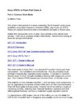
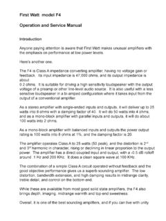
5 For the past twenty years or so I've been writing up single stage Zen amplifiers and other simple designs, and we are going to channel some of those to get what we want. Here is the very simplified circuit:In this circuit we see a single gain element Q1, an N-channel power Mosfet. In the diagram you will see that the three pins on this device are labeled Source, Drain and Gate. The input signal comes to the Mosfet Gate pin, and the output signals appears at the Drain pin. The Source is attached to circuit Ground. This arrangement is known as Common-Source operation. Of the three possible ways of operating a Fet gain device, it is the one that offers both voltage and current other two operating modes are known as Common-Drain and Common-Gate. Common-Drain has the signal input going to the Gate pin and takes the output from the Source pin.
6 It offers current gain, but not voltage gain. Common-Gate operation has input to the Source pin and takes the output from the Drain. It offers voltage gain but not current Common-Source Mosfet is operated single-ended Class A. This means that power goes into the circuit from one end only, and the transistor will be conducting current at all times through its operation. This current is delivered to the transistor through the Constant Current Source, which is a circuit which provided constant current, (ideally) no matter what the voltage conditions are. This constant current is shared by the Mosfet and the loudspeaker, and the input signal varies the degree to which these elements share this current, and this is what drives the will note that Common-Source operation intrinsically inverts the phase of the amplified signal, and so we have reversed the polarity of the output terminals to account for a concept, you can buy an integrated circuit constant current source, but we are going to design our own, partly to do-it-ourselves and partly because we want to alter its character a little to improve the performance of the circuit.
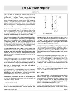
7 Here is the circuit with some details added showing the actual discrete circuit of our current source: FIRST we note that Q1 now actually has a part description IRFP240 which is a nice venerable power Mosfet which has been around for over 20 years. There is also Q2 which is the same type of Mosfet. Surrounding Q2 are several resistors, a small transistor Q3, and a capacitor. These elements are chosen to control Q2 in such a way that it acts as a DC constant current source which also varies AC-wise so as to favorably help the amplification provided by is used to set up the DC operation of Q2 by adjusting a constant DC voltage across C2. This sets the current source at a constant DC value by sensing the voltage drop from the Source of Q2 to the Drain of Q1 and keeping the it at the same value as the Base-Emitter voltage required to make Q3 conduct - about AC current of this circuit is made variable by tapping the output to the speaker from the midpoint of the power resistors R1 through R4.
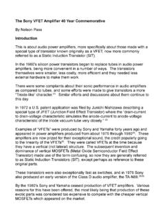
8 This sort of arrangement has several names, including SRPP and SEPP, but my favorite is mu follower .The above circuit does not yet make allowance for providing the correct DC voltage on the Gate pin of Q1 so as to conduct electricity. Also, there is not yet a provision for any negative feedback so as to create a low enough output impedance and low enough distortion to make the performance of the amplifier generally circuit below shows additions Q4, P1, C3, and R10 to accomplish these things. C3 allows us to set a DC voltage on the Gate of Q1 (about 4 volts) and we get this through P1 and R10. Q4, a Jfet transistor operated in Common-Drain mode provides a buffer that keeps the input impedance high. This will be helpful in driving the Q1 Gate capacitance when it comes time to enclose this circuit in a feedback loop while keeping the input impedance high enough that it doesn't have problems with the preamp circuits which might be driving this are a few more details to be added before we have the final circuit:Here you see the addition of the feedback loop formed by R12 and R11.
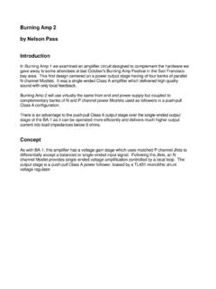
9 Also we have added R9 which sets the current value of Q4 and R6 which prevents parasitic oscillation in the Mosfet Q1. Mosfet Q2 has a similar Gate-stopper resistor with R5. R14 is used to bleed off DC voltage through C1, preventing thumps from the addition or removal of sources and of course we need an LED of some sort and a resistor for it, which would be this circuit results in a power amplifier which has 14 dB of voltage gain and 5 watts of output. The input impedance is 10 Kohm, and the damping factor is about output noise with the switching supply comes in around 100 is the curve of the gain of the amplifier into 8 ohms at 1 watt versus frequency. The upper curve is the gain without feedback, and the lower curve is with the approximately 9 dB of feedback provided in the design. The open loop bandwidth is about 70 Khz, and with feedback it is 200 Khz.
10 Here is a curve showing the distortion into 8 ohms at 1 Khz versus output power. At low power levels the distortion is second harmonic, with third harmonic appearing above 2 is the distortion vs frequency taken at 1 watt:ConstructionI designed the following PC board for this amplifier which is the one used at the FIRST Amp Camp event. It will be offered for sale by , and here is a picture of it, along with the mounting dimensions and is designed to mount on the flat surface of a heat sink with the output devices. Each channel of the amplifier has its own switching power supply and draws about 1 amp of current DC. The supply should be capable of delivering more than 2 amps of current short term. At 19 volts, the dissipation of the amplifier is about 20 watts, and the heat sink it is mounted on should not be allowed to get more than about 25 degrees Centigrade above the ambient temperature.