Transcription of AN INTRODUCTION TO FREQUENCY RESPONSE …
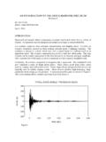
1 1AN INTRODUCTION TO FREQUENCY RESPONSE FUNCTIONSBy Tom IrvineEmail: 11, 2000_____IntroductionThe purpose of this report is to discuss FREQUENCY RESPONSE functions. These functionsare used in vibration analysis and modal testing. The purpose of modal testing is toidentify the natural frequencies, damping ratios, and mode shapes of a FrequenciesBridges, aircraft wings, machine tools, and all other physical structures have naturalfrequencies. A natural FREQUENCY is the FREQUENCY at which the structure would oscillateif it were disturbed from its rest position and then allowed to vibrate freely. Allstructures have at least one natural FREQUENCY . Nearly every structure has multiple occurs when the applied force or base excitation FREQUENCY coincides with astructural natural FREQUENCY . During resonant vibration, the RESPONSE displacement mayincrease until the structure experiences buckling, yielding, fatigue, or some other failure of the Cypress Viaduct in the 1989 Loma Prieta Earthquake is example offailure due to resonant excitation.
2 Resonant vibration caused 50 of the 124 spans of theViaduct to collapse. The reinforced concrete frames of those spans were mounted onweak soil. As a result, the natural FREQUENCY of those spans coincided with the frequencyof the earthquake ground motion. The Viaduct structure thus amplified the groundmotion. The spans suffered increasing vertical motion. Cracks formed in the supportframes. Finally, the upper roadway collapsed, slamming down on the lower AnalysisEngineers performing dynamic analysis must1. Determine the natural frequencies of the Characterize potential excitation Calculate the RESPONSE of the structure to the maximum Determine whether the expected RESPONSE violates any failure report is concerned with the first natural frequencies can be calculated via analytical methods during the design frequencies may also be measured after the structure, or a prototype, is natural FREQUENCY has a corresponding damping ratio.
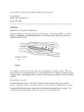
3 Damping values areempirical values that must be obtained by RESPONSE Function OverviewThere are many tools available for performing vibration analysis and testing. Thefrequency RESPONSE function is a particular FREQUENCY RESPONSE function (FRF) is a transfer function, expressed in the RESPONSE functions are complex functions, with real and imaginarycomponents. They may also be represented in terms of magnitude and FREQUENCY RESPONSE function can be formed from either measured data or FREQUENCY RESPONSE function expresses the structural RESPONSE to an applied force as afunction of FREQUENCY . The RESPONSE may be given in terms of displacement, velocity, oracceleration. Furthermore, the RESPONSE parameter may appear in the numerator ordenominator of the transfer RESPONSE Function ModelConsider a linear system as represented by the diagram in Figure 1.
4 () F is the input force as a function of the angular FREQUENCY . () H is the transferfunction. () X is the displacement RESPONSE function. Each function is a complexfunction, which may also be represented in terms of magnitude and phase. Each functionis thus a spectral function. There are numerous types of spectral functions. Forsimplicity, consider each to be a Fourier transform.() HTransfer function() FInput ForceDisplacement RESPONSE () X3 The relationship in Figure 1 can be represented by the following equations()()() = FHX (1)()()() = FXH (2)Similar transfer functions can be developed for the velocity and acceleration are six basic transfer functions as shown in Tables 1 and 1.
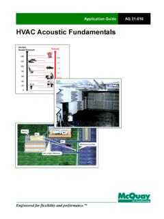
5 FREQUENCY RESPONSE Function NamesDimensionDisplacement / ForceVelocity / ForceAcceleration / ForceNameAdmittance,Compliance,Receptanc eMobilityAccelerance,InertanceTable 2. FREQUENCY RESPONSE Function NamesDimension Force / DisplacementForce / VelocityForce / AccelerationNameDynamic StiffnessMechanical ImpedanceApparent Mass,Dynamic MassNote that all of the functions in Tables 1 and 2 are related by algebraic equations. Any ofthe function can be calculated from any FREQUENCY RESPONSE FunctionConsider a single-degree-of-freedom system subjected to a force excitation as shown inFigure 2. The free-body diagram is shown in Figure 2. Single-degree-of-freedom SystemThe variables arem = mass,c = viscous damping coefficient,k = stiffness,x = absolute displacement of the mass,F = applied 3. Free-body DiagramSummation of forces in the vertical directionFmx= && (3)Fxkxcxm+ =&&& (4)Fxkxcxm=++&&& (5)m/Fx)m/k(x)m/c(x=++&&& (6) m kcx m kxxc&xFF5By convention,n2)m/c( = (7)2n)m/k( = (8)where n is the natural FREQUENCY in (radians/sec), and is the damping the convention terms into equation (6)
6 ,k/F2nx2nxn2x = + +&&& (9)The Fourier transform of each side of equation (9) may be taken to derive the steady-statetransfer function for the absolute RESPONSE displacement, as shown in Reference many steps, the resulting transfer function is + = )2(jk1n22n2n)(F)(X (10)This transfer function, which represents displacement over force, is sometimes called thereceptance function, as shown in Table transfer function can be represented in terms of magnitude and phase angle as()() + = 2n222n2n)(F)(X2k1 (11a)()() + = 2n222n)(F)(X21m1 (11b) =22nnarctan2 (12)6 The mobility function is + = )2(jjk1n22n2n)(F)(V (13)()() + = 2n222n2n)(F)(V2k1 (14a)()() + = 2n222n)(F)(V2m1 (14b) + =n22narctan2 (15)The accelerance function is + = )2(jk1n22n2n2)(F)(A (16)()() + = 2n222n2n2)(F)(A2k1 (17a)()() + = 2n222n2)(F)(A2m1 (17b)
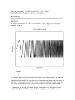
7 7 + =22nnarctan2 (18)ExampleConsider a single-degree-of-freedom system with parameters shown in Table 3. ParametersVariableSymbolValueMassm1 +05 N/mNatural Frequencyn 100 Hz ( rad/sec )Damping Ratio systems FREQUENCY RESPONSE functions are plotted according to Table 4. Thefunctions are plotted in terms of amplitude and 4. Plot FormatFunctionDescriptionFigureAdmittanc eDisplacement / Force3 MobilityVelocity / Force4 AcceleranceAcceleration / Force5 Dynamic StiffnessForce / Displacement6 Mechanical ImpedanceForce / Velocity7 Apparent MassForce / Acceleration8803060901201501801101001000 EXCITATION FREQUENCY (Hz)PHASE (degrees)ADMITTANCE PHASE ANGLE BY WHICH DISPLACEMENT LAGS FORCESDOF SYSTEM: mass= 1 kg fn = 100 Hz Damp = FREQUENCY (Hz)ADMITTANCE ( m / N )ADMITTANCE MAGNITUDE ( DISPLACEMENT / FORCE )SDOF SYSTEM: mass= 1 kg fn = 100 Hz Damp = FREQUENCY (Hz)PHASE ( degrees )MOBILITY PHASE ANGLE BY WHICH VELOCITY LAGS FORCESDOF SYSTEM: mass= 1 kg fn = 100 Hz Damp = FREQUENCY (Hz)MOBILITY ( m/sec / N )MOBILITY MAGNITUDE ( VELOCITY / FORCE )SDOF SYSTEM.
8 Mass= 1 kg fn = 100 Hz Damp = FREQUENCY (Hz)PHASE (degrees)ACCELERANCE ANGLE BY WHICH ACCELERATION LAGS FORCESDOF SYSTEM: mass= 1 kg fn = 100 Hz Damp = FREQUENCY (Hz)ACCELERANCE ( m/sec2 / N )ACCELERANCE MAGNITUDE ( ACCELERATION / FORCE )SDOF SYSTEM: mass= 1 kg fn = 100 Hz Damp = FREQUENCY (Hz)PHASE ( degrees )DYNAMIC STIFFNESS PHASE ANGLE BY WHICH FORCE LAGS DISPLACEMENTSDOF SYSTEM: mass= 1 kg fn = 100 Hz Damp = FREQUENCY (Hz)DYNAMIC STIFFNESS ( N / m )DYNAMIC STIFFNESS MAGNITUDE ( FORCE / DISPLACEMENT)SDOF SYSTEM: mass= 1 kg fn = 100 Hz Damp = FREQUENCY (Hz)PHASE (degrees)MECHANICAL IMPEDANCE PHASE ANGLE BY WHICH FORCE LAGS VELOCITYSDOF SYSTEM: mass= 1 kg fn = 100 Hz Damp = FREQUENCY (Hz)MECHANICAL IMPEDANCE ( N / m/sec )MECHANICAL IMPEDANCE MAGNITUDE ( FORCE / VELOCITY)SDOF SYSTEM: mass= 1 kg fn = 100 Hz Damp = FREQUENCY (Hz)PHASE (degrees)APPARENT MASS PHASE ANGLE BY WHICH FORCE LAGS ACCELERATIONSDOF SYSTEM: mass= 1 kg fn = 100 Hz Damp = FREQUENCY (Hz)APPARENT MASS (kg)APPARENT MASS MAGNITUDE ( FORCE / ACCELERATION)SDOF SYSTEM: mass= 1 kg fn = 100 Hz Damp = T.
9 Irvine, The Steady-state RESPONSE of a Single-degree-of-freedom SystemSubjected to a Harmonic Force, Publications, 1999.