Transcription of AN4275 Application note - st.com
1 August 2013 DocID024389 Rev 11/11AN4275 Application noteIEC 61000-4-5 standard overviewIntroductionThe objective of this document is to briefly explain the IEC 61000-4-5 standards and to show the benefits of having a range of protection devices specified according to this standard. For further details on IEC 61000-4-5 refer to the International Electrotechnical Commission web and consumer equipment are subjected to various surges. Here are the main ones: IEC 61000-4-2: ESD surges affect most of consumer equipment. The more stressful ESD standard is IEC 61000-4-2 (few tens of ns duration) but other standards such as human body model (HBM), machine model (MM) exist. IEC 61000-4-4: This standard is made to check the capability of the equipment to survive repetitive electrical fast transients and bursts. IEC 61000-4-5: Lightning and industrial surges modeled by IEC 61000-4-5. This is the one we will describe in this document. Telecommunication lines are exposed to lightning either directly on the equipment or due to induced effect because of ground potential addition to these surges, a telecommunication line may also be disturbed by either power induction or power contact with main AC lines.
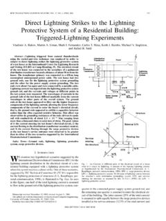
2 Depending on the country, these surges have been mainly modeled in: Telcordia GR-1089 core for America with 2/10 s and 10/1000 s surges ITU-T K series for the rest of the world with 10/700 s 61000-4-5AN42752/11 DocID024389 Rev 11 IEC 61000-4-5 Power lines are subjected to switching and lightning Power system switching transientsPower system switching transients can be separated into transients associated with: Major power system switching disturbances, such as capacitor bank switching Minor local switching activity or load changes in the power distribution system Resonating circuits associated with switching devices, such as thyristors Various system faults, such as short circuits and arcing faults to the grounding system of the Lightning transients The major mechanisms by which lightning produces surge voltages are the following: Direct lightning strokes to outdoor circuits injecting high currents and producing over voltages.
3 Indirect lightning strikes ( strikes between or within clouds or to nearby objects which produce electromagnetic fields) that induce voltages/currents on the conductors outside and/or inside a building. Lightning ground current flows resulting from nearby direct-to-earth discharges coupling into the common ground paths of the grounding system of the installation. The rapid change of voltages and flows of current which can occur as a result of the operation of a lightning protection device can induce electromagnetic disturbances into adjacent equipment. Target of the IEC 61000-4-5 is to provide a model to simulate these surges and then to be able to check if the equipment is able to survive Rev 13/11AN4275 IEC 61000-4-5 definition2 IEC 61000-4-5 Classes and voltage levelsThe standard specifies different classes depending on where the equipment is installed. For each class a corresponding peak voltage is applicable (see Table 1). Starting at a 500 V surge, it is generally required to protect the equipment with a specific Surge generatorThe generator used to model the surge is described in Figure 1.
4 IEC 61000-4-5 surge generatorIn open mode, the generator delivers a s/50 s voltage waveform, and in short circuit, the current waveform is 8/20 s. This kind of generator is called a combination wave generator. The surge is shown on Figure 2 and Figure 1. Classes and voltage levelsClassEnvironmentVoltage level0 Well protected environment, often in a special room25 V1 Partially protected environment500 V2 Electrical environment where the cables are well separated, even at short runs1 kV3 Electrical environment where power and signal cables run in parallel2 kV4 Electrical environment where the interconnections include outdoor cables along with the power cable, and cables are used for both electronics and electric circuits4 kV5 Electrical environment for electronic equipment connected to telecommunication cables and overhead power lines in a non-densely populated areaTest level s/50 s surge generator sourceRout= 2 WRextIEC 61000-4-5 definitionAN42754/11 DocID024389 Rev 1 Figure 2.
5 Voltage waveform in open circuit Figure 3. Current waveform in short circuitFor the same environment, there is a distinction between power lines and data lines, and an additional serial resistance (Rext) may be required between the DUT (device under test) and the surge selection of the source impedance (Rout + Rext) depends on the kind of equipment to be protected: The 2 impedance represents the source impedance of the low-voltage power supply network. The generator is used alone with its effective output impedance of 2 . The surge is applied in a differential mode. The 12 (10 + 2 ) impedance represents the source impedance of the low-voltage power supply network and ground (common mode). A generator with an additional resistor of 10 in series is used. The effective 42 (40 + 2 ) impedance represents the source impedance between all other lines and ground. A generator with an additional resistance of 40 in series is protection devices are sized with the surge current, Table 2 shows the maximum peak current values depending on voltage level and Rext when surge generator is short ,2 s 30%TAO10,00,10,30,50,91,0 UtB50 s 20%30% ,00,10,50,91,0 ItB2 20 %0 s8 20% s30% Rev 15/11AN4275 IEC 61000-4-5 definition Test schematics are shown in Figure 4 and Figure 4.
6 Differential mode test set-upFigure 5. Common mode test set-upTable 2. Maximum peak current values depending on voltage level and RextClass 0 Class 1 Class 2 Class 3 Class 425 V500 V1 kV2 kV4 kVReq = 42 A12 A24 A48 A96 AReq = 12 A42 A84 A167 A334 AReq = 2 A250 A500 A1000 A2000 ALNPED ecoupling networkCombinationwave generatorAC (DC)power supply networkRext= 0 Equipmentunder testLNPERext= 10 Decoupling networkCombinationwave generatorAC (DC)power supply networkEquipmentunder testIEC 61000-4-5 definitionAN42756/11 DocID024389 Rev 1 Figure 4 and Figure 5 show the test schematics when the equipment is connected to power other types of lines, the decoupling network is slightly different on both line-to-line and line-to-ground tests. Furthermore the test must be done with Rext = 40 (see Figure 6).Figure 6. IEC 61000-4-5 multi-line test set-upIn practice, this surge is applied to equipment and not to a specific protection the protection device is directly located at the input of the equipment, the protection device has to withstand the complete surge.
7 In some cases, the protection device is not located at the input but somewhere in the middle of a board and then the protection device sees a slightly different Decoupling networkCombinationwave generatorEentquipmunder testProtectionequipmentAuxillaryequipmen tDocID024389 Rev 17/11AN4275 Protection devices3 Protection devicesThe device used to protect against IEC 61000-4-5 is generally a clamping device located in parallel with the circuit to be protected. This protection device limits the voltage to a specified value VCL (Clamping voltage) by absorbing the surge current. Its surge current capability is specified in its datasheet: IPP (peak pulse current).Figure 7 gives the I/V characteristics of a clamping 7. I/V characteristics of a unidirectional clamping devicesThe goal of a protection device is to survive the surge (IPP), and to protect the equipment by limiting the surge voltage (VCL) below the maximum admissible voltage of the protectionThe IPP of the protection must be defined according to the surge.
8 In order to withstand a surge, a protection device should have an IPP (8/20 s surge) higher than the peak current generated by the standard. It is worthless to choose a protection defined by a 10/1000 s surge (this surge is dedicated to telecommunication lines) when the standard requires to comply with 8/20 has been specifying its protection devices with 10/1000 s and 8/20 s surges for years. Trends toward optimized protection in cost and in size leads us to produce dedicated protection devices specified according to IEC protectionTo protect a circuit from a surge, the protection device should have a VCL (8/20 s surge) lower than the maximum voltage the circuit can a unidirectional device is safer as clamping voltage will be limited to VCL in one direction and to a forward voltage on the other device must be used only if the Application requires to accept a reverse plug-in (on DC power lines) or if located on AC areaWorking areain case ofpositive surgesWorking areain case ofnegative surgesIppPEP01-5841 as an exampleAN42758/11 DocID024389 Rev 14 PEP01-5841 as an exampleThis device is dedicated to the protection of power supplies of PoE in PSE side.
9 Typically PoE power supply is 0 to -48 V. This protection device embeds 4 cells to protect against IEC 61000-4-5 1 kV under 42 which leads to a 24 A surge is given on Figure 8. PEP01-5841 functional diagramAs the PEP01-5841 has been designed to protect against IEC61000-4-5, specified current capability (IPP) of each cell is 24 A (Figure 8).This complies with the IPP protection requirement (capability to withstand the surge). The capability to protect is achieved with the VCL max limited to 100 V. The reason for the 100 V max is to avoid failure of the Pmos or the PSE controller generally using a technology typically around 110 or 120 V rated 100 V in the 3. Electrical characteristics - values (Tamb = 25 C)TypeIRM max @ VRMVBR @IR (1)1. Pulse test: tp < 50 ms8/20 sVCL To calculate maximum clamping voltage at other surge level, use the following formula:VCLmax = RD x IPP + VBRmax25 C85 A AVVmAVA Gnd pins must be connected to GndDocID024389 Rev 19/11AN4275 Conclusion5 ConclusionIn most countries it is mandatory to comply with the IEC 61000-4 of the protection devices are rated with ESD capability but only a few of them are rated with the surge corresponding to IEC 61000-4-5.
10 Using the correct protection designed to comply with IEC 61000-4-5 is an insurance to get reliable equipment and to avoid costly quality field returns to keep a good brand has developed a range of devices rated according to IEC 61000-4-5. For more information, go to the web site and follow the links to the products for power discretes and modules for protection devices. IEC 61000-4-5 compliant devices are listed under EOS 8/20 microsecond surge protection (see Figure 9).Figure 9. EOS 8/20 s surge protectionThe use of an IEC 61000-4-5 rated protection limits the number of tests to be performed before certification, saves cost and time and reduces the number of quality historyAN427510/11 DocID024389 Rev 16 Revision history Table 4. Document revision historyDateRevisionChanges06-Aug-20131 Initial Rev 111/11AN4275 Please Read Carefully:Information in this document is provided solely in connection with ST products.