Transcription of AN4775 Application note - st.com
1 March 2016 DocID028454 Rev 11/231AN4775 Application noteBasics and low-cost solution proposals to move from legacy connector to USB Type-C connector with STM32 devicesIntroductionThe USB Type-C and the Power Delivery is certainly one of the most promising technology to simplify our daily life and to enhance our consumer and mobile user new reversible USB Type-C connector makes the plug insertion more user friendly. The technology offers a single platform connector to carry all necessary data (including video), and using Power Delivery protocol allows to negotiate up to 100W of power to supply or charge equipment connecting to this USB port. Less cables, less connectors and universal chargers are the final the USB Type-C connector supports up to 15W (5V @ 3A) of power, extended to 100W (up to 20V @ 5A) with the optional USB Power Delivery of power is far enough for most of hundred of million of legacy USB powered devices actually on the Application note is a guideline to introduce this USB Type-CTM connector onto platform to replace legacy connectors.
2 It introduces some basis of the two new standards USB Type-C and the USB Power document proposes some schematics to replace in a simple way legacy connector by USB Type-C one on platform using b l e 1 provides the list of products to which this Application note applies. Table 1. Applicable productsTypeSeriesMicrocontrollersSTM32L 0 SeriesSTM32L1 SeriesSTM32L1W SeriesSTM32L4 SeriesSTM32F0 SeriesSTM32F1 SeriesSTM32F2 SeriesSTM32F3 SeriesSTM32F4 SeriesSTM32F7 Rev 11 USB Type-C in a nutshell .. Type-C vocabulary .. mandatory feature set .. pin mapping .. power options .. 82CC Pins .. orientation/cable twist detection .. Capability detection and usage ..113 USB power delivery .. delivery signaling .. Structure .. Power .. 134 Alternate modes .. pins re-assignment .. 155 Converting STM32xx device only to USB Type-C platform 166 Converting STM32xx host to USB Type-C platform.
3 177 Converting legacy STM32xx OTG to USB Type-C platform 188 Conclusion .. 209 References .. 2110 Revision history .. 22 DocID028454 Rev 13/23AN47753 Figure plug form factors.. 5 Figure Type-C receptacle pinout.. 7 Figure up/down CC detection .. 10 Figure * signaling .. 12 Figure available for reconfiguration over the Full Featured Cable .. 14 Figure available for reconfiguration for direct connect applications .. 15 Figure device using USB Type-C receptacle .. 16 Figure host using USB Type-C receptacle .. 17 Figure OTG using USB Type-C receptacle .. 18AN47754/23 DocID028454 Rev 1 Table products .. 1 Table Type-C receptacle pinout meaning .. 8 Table supply options .. 9 Table CC termination (Rp) requirements .. 11 Table CC Termination (Rd) Requirements .. 11 Table on Sink CC pins (Multiple Source Current Advertisements).
4 11 Table revision history .. 22 DocID028454 Rev 15/23AN4775 USB Type-C in a nutshell221 USB Type-C in a nutshellThe USB Implementers Forum (USB-IF) introduces two complementary specifications: The USB Power Delivery (PD) specification details how a link can be transformed from a power source (900mA at 5V on VBUS) to a 100W power or consumer source (up to 5A at 20V). The USB Type-C cable and connector specification details a reversible, slim connector system based on high speed signals and two SuperSpeed lanes at up to 10 Gbps, which can also be used to support Alternate new connector is designed to be non-polarized and fully reversible, no matter which way it is such, this new reversible 24-pin USB Type-C plug is aimed to be an universal connector with all the advanced features proposed by Power Delivery: negotiating power roles, negotiating power sourcing and consumption levels, performing active cable identification, exchanging vendor specific sideband messaging, performing Alternate Mode negotiation,allowing third-party communication protocols to be routed onto the reconfigurable pins of the USB Type-C 1.
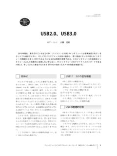
5 USB plug form factors069 9 D h^ h D D USB Type-C in a nutshellAN47756/23 DocID028454 Rev 1 The USB Type-C cables use the same male connector on both is also important to mention that USB Type-C supports all prior protocols from onward, including the driver stack and power capability. The new connector is quite small as it is only wide by depicted in Figure 1, the new USB Type-C plug allows to have single connector to cover all features provided by previous plugs which improve USB facility usage for all customers because of its flexibility in data and power Type-C connection allows port to be in host-mode only, device-mode only or dual role and both data and power roles can be independently and dynamically swapped using USB Power Delivery commands.
6 USB Type-C vocabularyThe terminology commonly used for USB Type-C system is: Downstream Facing Port (DFP): Associated with the flow of data in a USB connection. Typically the ports on a host or on a hub to which devices are connected. In its initial state, the DFP sources VBUS and VCONN and supports data. A charge only DFP port only sources VBUS Upstream Facing Port (UFP): Associated with the flow of data in a USB connection. The port on a device or a hub that connects to a host or the DFP of a hub. In its initial state, UFP sinks VBUS and supports data. Dual Role Port (DRP): Refers to a USB port that can operate as either a source or a sink. The role of the port offers may be fixed to either source or sink or may alternate between the two port states. Initially when operating as a source, the port also takes role of a DFP and when operating as a sink, the port takes a role of a UFP.
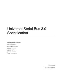
7 The port role may be change dynamically either to reverse power or data roles. Source: Port asserting Rp (Pull up resistor. See Figure 3) on CC (Command Control pins. See Chapter 2) pins and providing power over VBUS (5V to 20V and up to 5A), most commonly a Host or Hub DFP (like legacy Type-A port) Sink: Port asserting Rd (Pull down resistor. See Figure 3) on CC pins and consuming power from VBUS (5V to 20V and up to 5A), most commonly a device (like legacy Type-B port) Minimum mandatory feature setUSB Type-C port are not required to implement and supports all of the advanced features that are defined within all minimum features which need to be supported by the system are: Cable attach and detach detection Plug orientation/cable twist detection connectionDocID028454 Rev 17/23AN4775 USB Type-C in a Connector pin mappingThe 24-pins USB Type-C includes symmetric connections: differential pairs (D+/D-) Power pins.
8 VBUS/GND asymmetric connections Two sets of Tx/Rx signal paths which support data speed configuration channels (CC lines) which handles discovery, configuration and management of USB Type-C power delivery features Two Side Band Use (SBU lines) signals are present for analog audio modes and may be used by alternate modeFigure 2. USB Type-C receptacle pinoutD^s s 'E Zy н Zy s h^^ h н s h^dy dy н 'E 'E dy н dy s h^ н ^ h s h^Zy Zy н 'E USB Type-C in a nutshellAN47758/23 DocID028454 Rev VBUS power optionsTable 1. USB Type-C receptacle pinout meaningPinNameDescriptionCommentA1 GNDG round returncan be up to 5A split into 4 pinsA2TX1+ datalines or Alternate10Gb TX differential pair in powermax power is 100W (20V - 5A) split into 4 pinsA5CC1 or VCONNC onfiguration Channel or power for active or electronically marked cableIn VCONN configuration, min power is 1WA6D+ datalinesA7D-A8 SBU1 Side Band UseAlternate mode onlyA9 VBUSBus powermax power is 100W split into 4 datalines or Alternate10Gb RX differential pair in +A12 GNDG round returncan be up to 5A split into 4 pinsB1 GNDG round returncan be up to 5A split into 4 pinsB2TX2+ datalines or Alternate10Gb TX differential pair in powermax power is 100W split into 4 pinsB5CC2 or VCONNC onfiguration Channel or power for active or electronically marked cableIn VCONN configuration.
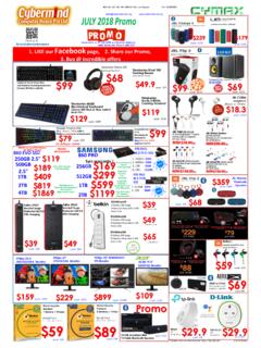
9 Min power is 1WB6D+ datalinesB7D-B8 SBU2 Side Band UseAlternate mode onlyB9 VBUSBus powermax power is 100W split into 4 datalines or Alternate10Gb RX differential pair in +B12 GNDG round returncan be up to 5A split into 4 pinsDocID028454 Rev 19/23AN4775 USB Type-C in a nutshell22 VBUS provides a path to deliver power between a host and a device and between a charger and a options available from a perspective of a device with a USB Type-C connector are listed : USB Type-C to Type-C cable assembly needs VBUS to be protected against 30V DC at cable rated current (3A or 5A).Table 2. Power supply optionsMode of OperationNominal VoltageMaximum current based on to chargingUSB Type-C high power devicesUSB Type-C Current@3A5V3 AUSB PDUp to 20 Vup to 5 ADirectional control and power level managementCC PinsAN477510/23 DocID028454 Rev 12 CC PinsThere are two CC pins in receptacle but only one CC pin is connected in cable per plug facing both CC1 and CC2, DFP must have Rp pull up resistors, whereas UFP must have Rd pull down cables need to provide impedance Ra to ground on VCONN Plug orientation/cable twist detectionAs USB Type-CTM can be inserted in the receptacle in either orientation, it is mandatory to first detect the orientation.
10 The detection is done thru CC lines using Rp/Rd a DFP exposes Rp terminations on its CC pins and a UFP exposes Rd terminations on its CC detect the connection, the DFP monitor both CC 3. Pull up/down CC detection069 9 &DEOH&& && && && 5S5S5G5G ')3 PRQLWRUV IRU FRQQHFWLRQ')3 PRQLWRUV IRU FRQQHFWLRQ8)3 PRQLWRUV IRU RULHQWDWLRQ8)3 PRQLWRUV IRU RULHQWDWLRQ&&5D5 DDocID028454 Rev 111/23AN4775CC Power Capability detection and usageUSB Type-C power has initially two main power options: and 3A on top on default USB supply capability of the port to the device depends on Rp pull up resistor value on capability can be negotiated using USB Power Delivery b l e 3 below shows the different possible must also implement on both CC1 and CC2 Rd pull down resistors for biasing the detection system and to be identified as power which is able to detect power capability needs to monitor CC lines voltage accurately in order to determine power capability of 3.