Transcription of Analog Current Output Type Ambient Light Sensor IC - …
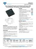
1 1/8 - 2012 ROHM Co., Ltd. All rights reserved. Ambient Light Sensor ICs Analog Current Output Type Ambient Light Sensor IC BH1603 FVC Descriptions BH1603 FVC is an Analog Current Output Ambient Light Sensor . BH1603 FVC is the most suitable to obtain the Ambient Light data for adjusting LCD and Keypad backlight of Mobile phone for power saving and better visibility Features 1) Compact surface mount package mm 2) Spectral sensitivity close to human eyes sensitivity. 3) Output Current in proportion to brightness. 4) Minimum supply voltage 5) Built-in shutdown function 6) 3 steps controllable Output Current gain. 7) logic input interface 8) Low sensitivity variation (+/-15%) Applications Mobile phone, LCD TV, PDP TV, Laptop PC, Portable game console, Digital camera, Digital video camera, PDA, LCD display Absolute Maximum Ratings Parameter SymbolLimits UnitsSupply Voltage Vmax 7 V Operating Temperature Topr -40 85 C Storage Temperature Tstg -40 100 C Iout Current mAPower Dissipation Pd 260 mW 70mm 70mm glass epoxy board.
2 Derating at C for operating above Ta=25 C. Operating Conditions Parameter UnitsVCCV oltage VCC VCC Electrical Characteristics ( VCC = , Ta = 25 C, unless otherwise noted ) Parameter UnitsConditions Supply Current1 (Operate) Icc1 51 74 97 uAEv=100 lx (H-Gain Mode) Supply Current2 (0 lx) Icc2 lx (H-Gain Mode) Supply Current3(Shutdown) Icc3sd- GC2=0 No Input Light IOUT Output Current1 (Dark Current ) Iout1 - - lx IOUT Output Current2 Iout2 51 60 69 uAEv=100 lx (H-Gain Mode) Peak Wave Length p - 560- nm Incandescent/Fluorescent Light Current Ratio rIF - times Ev=100 lx Saturated Output Voltage VOMAX Ev=100 lx, RL=220k (H-Gain Mode) GC1, GC2 Input L Voltage VIL 0 - GC1,GC2 Input H Voltage1 VIH1 VccV VCC GC1,GC2 Input H Voltage2 VIH2 VccV VCC Wake-up Time twu - 45 128us Shutdown H-Gain Mode ,Ev=100lx Gain Ratio H-Gain Mode/M-Gain Mode rHM times Ev=100lx Gain Ratio M-Gain Mode/L-Gain Mode rML times Ev=100lx White LED is used as optical source Technical Note 2/8 - 2012 ROHM Co.
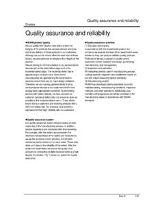
3 , Ltd. All rights reserved. Reference Data IOUT VCC dependency Light Source Dependency ( Fluorescent Light is set to '1' ) IOUT Temperature dependency ( 100 lx ) Spectral Response Illuminance IOUT Characteristics Directional Characteristics 1 Directional Characteristics 2 Ta IOUT ( 0 lx ) Ta ICC ( 0 lx ) Illuminance Wake up Time [ deg ] [ deg ]Ratio- + - + 1pin 1pin [ nm ] -20020 40 60 80 100Ta [ C ]IOUT [ uA ]L-Gain H-Gain SD M-Gain [ C ]ICC [ uA ]H-Gain M-Gain SD L-Gain 0 20406080100Ta [ C ] [ V ]RatioH-Gain L-Gain M-Gain Illuminance [ lx ]Illuminance [ lx ] LightIncandescent LightHalogen LightKripton LightArtifical Sun LightWhite LEDR atio- + - + 0.
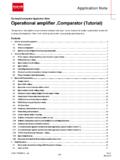
4 0010. 010. 11101001000100001000000110010,0001,000,0 00 IOUT [ uA ]H-Gain M-Gain L-Gain 110100100010000100100010000 WakeupTime [ us ]BH1603 FVC Technical Note 3/8 - 2012 ROHM Co., Ltd. All rights reserved. Block Diagram Block Diagram Descriptions PD Photo diode close to human eyes sensitivity. Current AMP To amplify Photo diode Current ( H-Gain / M-Gain / L-Gain ) Gain controllable in 3 steps by input voltage from GC1 and GC2. Logic Logic block for mode setting by input voltage from GC1 and GC2 Mode Setting GC2 GC1 Mode 0 0 Shutdown 0 1 H-Gain Mode 1 0 M-Gain Mode 1 1 L-Gain Mode
5 VCC GC1 PD IOUT R1 CurrentAmp GND LogicGC2 C1 BH1603 FVC Technical Note 4/8 - 2012 ROHM Co., Ltd. All rights reserved. External parts Setting 1) Gain setting of BH1603 FVC Please select the best gain controlled by 5 and 6pin based on the required illuminance range. The reference is as follows. Illuminance detection range [lx] Gain Mode ~1,000 H-Gain Mode ~10,000 M-Gain Mode ~100,000 L-Gain Mode This device will be mounted under the optical window in actual designing.
6 Therefore, there is a possibility that the illuminace to ALS( Ambient Light Sensor ) will be less than the illuminance on the final product surface. Please consider the attenuation of Light through the optical window. Please set Output resistance value( R1) within the range of 1 k ~1M which needs to be smaller than the input impedance of the next circuit. 2) Approximate formula of IOUT Output voltage in each Gain Mode (1) H-Gain mode The Output voltage is calculated as below. Viout= x 10-6 x Ev x R1 Viout is IOUT Output voltage [V]. Ev is an illuminance of the ALS surface [lx]. R1 is IOUT Output resistor[ ]. (For example) In case you want to convert the illuminance value up to 500 lx by ADC. If the maximum voltage of ADC input is 2V, Output resistor value will be as below.
7 R1 = Viout/( x 10-6 x Ev) = 2 /( x 10-6 x 500) = 6667[ ] [k ] (2) M-Gain mode The Output voltage is calculated as follows. Viout= x 10-6 x Ev x R1 (3) L-Gain mode The Output voltage is calculated as follows. Viout= x 10-6 x Ev x R1 3) C1 (1) To reject the flicker In case IOUT Output is R1 only and an ALS receives the artificial lights such as fluorescent lamps and incandescent lamps synchronized with 50/60 Hz of AC power supplies, the Output Current has a ripple. If you want to reject this ripple, please add C1 to R1 in parallel. Please set it to C1 x R1 = about as a time constant. (2) To control backlight smoothly by using illuminance value. C1 is effective to control backlight smoothly for a rapid changing of the illuminance.
8 In this case, please set it to C1 x R1 = about 1 ~ 10 as a time constant. It is not necessary if you average illuminance value with software to change backlight smoothly. Please note that the rise time becomes slow at power-on and recovery from shutdown mode to operation mode. BH1603 FVC Technical Note 5/8 - 2012 ROHM Co., Ltd. All rights reserved. Terminal Descriptions Pin No. Pin Name Equivalent Circuit Function 1 IOUT This terminal outputs Current depending on illuminance level. Use this pin by putting resistor between GND. 2 GND GND Terminal 3 VCC Power Supply Terminal 4 NC NC( Non connection)Terminal Open or short to GND 5 GC1 Mode Setting Terminal 1 6 GC2 Mode Setting Terminal 2 VCCVCC VCCBH1603 FVC Technical Note 6/8 - 2012 ROHM Co.
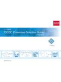
9 , Ltd. All rights reserved. Package Outlines Optical design for the device WSOF6 ( Unit : mm ) mm mm PD area ( mm x mm ) Please design an optical window to have the focused Light within this area. mm mm mm mm Lot No. Production code A G BH1603 FVC Technical Note 7/8 - 2012 ROHM Co., Ltd. All rights reserved. Notes for use 1) Absolute Maximum Ratings An excess in the absolute maximum ratings, such as supply voltage ( Vmax ), temperature range of operating conditions (Topr), etc., can break down devices, thus making impossible to identify breaking mode such as a short circuit or an open circuit. If any special mode exceeding the absolute maximum ratings is assumed, consideration should be given to take physical safety measures including the use of fuses, etc.
10 2) GND voltage Make setting of the potential of the GND terminal so that it will be maintained at the minimum in any operating state. Furthermore, check to be sure no terminals are at a potential lower than the GND voltage including an actual electric transient. 3) Short circuit between terminals and erroneous mounting In order to mount ICs on a set PCB, pay thorough attention to the direction and offset of the ICs. Erroneous mounting can break down the ICs. Furthermore, if a short circuit occurs due to foreign matters entering between terminals or between the terminal and the power supply or the GND terminal, the ICs can break down. 4) Operation in strong electromagnetic field Be noted that using ICs in the strong electromagnetic field can malfunction them.