Transcription of Analysis and Design of Input Filter for DC-DC Circuit
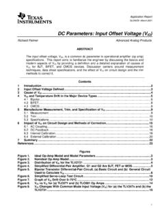
1 1 SNVA801 November2017 SubmitDocumentationFeedbackCopyright 2017,TexasInstrumentsIncorporatedAnalysi sand Designof InputFilterfor DC-DCCircuitApplicationReportSNVA801 November2017 Analysisand Designof InputFilterfor DC-DCCircuitCharlesZhangABSTRACTW hendesigningDC-DCcircuits,it is commonto add the inputfilter circuitbeforethe LCfilter is one of mostfrequentlyusedinputfilter ,if a designis not optimal,inputfilter circuitmaycauselargeoutputnoiseinsteadof suppressingthe noise,and influenceof the inputfilteron the DC-DCcontrollooptransferfunction,and the influenceof a closedloopon the inputfilter,explainswhy inputfiltercausesunexpectedproblem,and suggestshow to eliminatethe side effectof the BuckWithInputLC the the InputImpedanceon trademarksare the propertyof + GNDAPCinUinILIOIOU loadRCRCLLR+ GNDAPC+ inU inI LI OI OU LI d inU d 1 : DloadRCRCLLR inLLCP ininiI dDiuU dDuFunctionof November2017 SubmitDocumentationFeedbackCopyright 2017,TexasInstrumentsIncorporatedAnalysi sand Designof InputFilterfor DC-DCCircuit1 Functionof InputFilterCircuitInputfiltersare widelyusedin mainpurposes.
2 One is to suppressthe noiseand surgefromthe frontstagepowersupply,anotheris to decreasethe interferencesignalat switchingfrequencyand its harmonicfrequencyto go backto the powersupplyand interfereotherdeviceswhichusesthe inputfilter designis very importantto passthe electromagneticcompatibility(EMC) passivefiltersare amongthe commonfiltersfor attenuatethehigh frequencynoisefromthe powersupplyand can also suppressthe switchingnoiseto go backto LC Filter is not well damped,the frequencyresponsewill peaknearresonantfrequency,whichmeansthe LC actuallyis amplifyingthe amplification,sometimes,LC Filter designalso has effecton the controlloop of the DC-DCconverter,somepoorLC Filter will decreasethe phasemarginand degradethe transientresponseperformance, isdiscussedin Section2 basedon a BuckWithInputLC is a on and off statusof one switchingcycle,FET the averagemodel.
3 The smallsignalof inputcurrentandswitchingnodevoltagecan be calculatedas Equation1, and the openloop smallsignalmodelof the buckcan be expressedas Figure2.(1)Figure1. BuckCircuitTopologyFigure2. BuckCircuitSmallSignalModelIt is normalthat inputvoltageand outputcurrentmay change,whichinfluencesthe control,duty cyclemay changeto maintainthe outputvoltage,at the sametime,the inductorcurrentwill we can buildthe openloop controlblockdiagramas 2( ), ( )( ), ( ) ( )( )1( )|| (1)( )( ) ooLiiRind s i sd s i sinLu su sR LCssZ s DRCsi si sD 2 ( ), ( ) ( )1( )| 1( ) iLiid s u sLRoi s G s LCssi s 2( ), ( ) ( )(1)( )| ( )1 oDLRiud s i sLiRi sRCsG s u sLCss 2 ( ), ( ) ( )(1)( )| 1( )
4 InioULRidu s i sLRi sRCsG s LCssd s 2 ( ), ( ) ( ) ( )| 1( ) iooutd s u sLRou sLsZsLCssi s 2( ), ( ) ( ) ( )| ( )1 oouud s i sLiRu sDGsu sLCss 2 ( ), ( ) ( ) ( )| 1( ) iooiudu s i sLRu sUGsLCssd s iu ou oiGud dGuuZoutGidGiuGii BuckWithInputLC Filter3 SNVA801 November2017 SubmitDocumentationFeedbackCopyright 2017,TexasInstrumentsIncorporatedAnalysi sand Designof InputFilterfor DC-DCCircuitFigure3. Open-LoopBuckControllerBlockDiagramFor simplicity,ignorethe inductorDCRand outputcapacitorESRwhencalculatedthe six transferfunctionsin Figure3 are calculatedas Equation2 to Equation7.
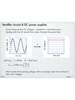
5 All the six transferfunctionswill be usedin followingsections, (2)(3)(4)(5)(6)(7)Inputimpedanceis a key parameterin this paper,whichis not obviousto drawnin Figure3; nevertheless,openloop inputimpedancecan be definedand calculatedas Equation8 usinga similarmethod.(8)Gc iu ou refu oiGmHGud cu dGuuZoutGidGiuGii Li erruLoopGainof BuckWithInputLC November2017 SubmitDocumentationFeedbackCopyright 2017,TexasInstrumentsIncorporatedAnalysi sand Designof InputFilterfor the BuckConverterFor a buckconverter,it is normallydesiredthat the outputvoltageis usedto closethe controlloop,it automaticallychangesthe duty cycleto decreaseor eveneliminatetheinfluencefromthe inputvoltageor typicalclosedloop of VMCbuckconverteris the feedbackresistornetwork,Gcrepresentsthe erroramplifier,andGmis for the VMCC losedLoopBuckControllerBlockDiagramBy adoptingclosedloop topology.
6 Loop gain is definedas the productof the gainsin feedforwardpathandfeedbackpathin the closedloop as Equation9. Takethe VMCplus type III compensatoras example,thefrequencyresponseofTloopcan be plottedas (s) = HGcGmGud(9)Figure5. LoopGainFrequencyResponse+ inUInputfilterDCDCC onverterPower stageloadRController dfilterZinZ_2( ) ( ) 1( )(1( )) (1) outout CLLlooploopRZsLsZsTsTsLCss_2( ) ( ) 1( )(1( )) (1) uuuu BuckWithInputLC Filter5 SNVA801 November2017 SubmitDocumentationFeedbackCopyright 2017,TexasInstrumentsIncorporatedAnalysi sand Designof InputFilterfor DC-DCCircuitUnderthe effectof the closedloop,the transferfunctionfromthe perturbationto the outputvoltageismultipliedby a factor1 /(1 + T(s)).
7 The closedloop audiosusceptibilityand outputimpedancecan beexpressedas Equation10 and Equation11. And the openloop and closedloop frequencyresponsecanbe drawnas Figure6 and Figure7, it can be seenfromthe picture,low frequencyperturbationcan be wellsuppressedby closingthe controlloop.(10)(11)Figure6. ClosedLoopAudioSusceptibilityFigure7. FilterEventhoughclosedloop suppressesthe audiosusceptibilitya lot at low frequency,but it doesn t changetoo muchfor the middleand high designershouldalso considerthe interferencefromtheDC-DCbackto the powerbus. Thus,a LC Filter is oftenusedfor DC-DCcircuitto passEMI Filter to solvean EMI problem,anotherproblemmay arise,whenthe load transientperformancechanges,audiostabili tybecomesworseat somefrequency,someevencausethe be explainedas that inputfilter circuitmodifiesthe transferfunctionof thebuckconverter,includingthe controlto outputtransferfunctionGud, whichthenchangesthe loop gain,phasemargin, Middlebrook s extraelementtheorem,addingthe Filter circuitto the buckconverteraddsacorrectionfactorto the BuckControlBlockDiagramWithLC Filter ( ) 02( )( ) |o oNinu sRZsZ sD2 2( ) 01( )( ) |1 LRDind s R LCssZ sZ sDRCs ( )
8 D s 1( )|| filterfDCRESRfZssLRRsC( ) 0( ) | filterudZsGs _( ) 0( ) 1( ) ( )( ) |( ) 1( ) filterfilterNudfudZsfilterDZsZsGsGsZsZ s LoopGainof BuckWithInputLC November2017 SubmitDocumentationFeedbackCopyright 2017,TexasInstrumentsIncorporatedAnalysi sand Designof InputFilterfor DC-DCCircuitwhere is the originaltransferfunctionbeforeadditionof inputfilter.(12)is the outputimpedanceof the LC Filter , the converterinputimpedance,withset to the converterinputimpedance,with the outputnulledto poorlydesignedLC Filter as an example,afteradditionof correctfactor,the new loop gain transferfunctioncan be calculatedfromEquation13.
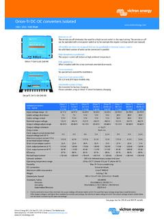
9 The frequencyresponsecan be calculatedas Figure9,simulatedas Figure10 usingSimplis,the two waveformsshowgoodconsistencyof the LC (s) = HGcGmGud_f(13)Figure9. MathcadCalculationLoopGainFigure10. SimplisSimulationLoopGainComparingthe new frequencyresponsewaveformwith originalone,it can be easilyfoundthat the LCfilter bringsa dip to the originalfrequencyresponse,the magnitude-frequencycurvedropsto closeto 0 dbin this case,and the phase-frequencycurvealso dropsnearthat point,whichmakesthe loop gainperformanceworse. iu ini1(1)1 uu loopLloopinIloopTDITZUTHGcGm Li iu ouILD ini1uucmudGHG G G dGid1cmudiucmuuHG G GGHG G G Gc iu ouGmHGud cu dGuuGidGiu LiGidDIL ini1,, uuudiuuuidudIininGDGDGG November2017 SubmitDocumentationFeedbackCopyright 2017,TexasInstrumentsIncorporatedAnalysi sand Designof InputFilterfor openloop inputimpedanceis definedas Equation8, afterapplyingthe closedloop,the closedloopchangesthe inputimpedance,becausewheninputvoltagech ange,duty cyclechangesto maintaintheoutputvoltage,whichalso bringsadditionalchangeto the calculatethe closedloop inputimpedance,combinedwith Equation1, the blockdiagramcan be drawas Figure11.
10 By changingthe feedbackand feed-forwardposition,a simplifiedblockdiagramcan bedrawnas in Figure12. By comparingEquation2 throughEquation8, it can be calculatedthat(14)combinedwith Figure12, a singleblockfrominputvoltageto inputcurrentcan be expressedas ClosedLoopInputImpedanceCalculationBlock DiagramFigure12. SimplifiedClosedLoopInputImpedanceCalcul ationBlockDiagramFigure13. SingleBlockFromInputVoltageto InputCurrent___ ( )(1)( ) ( ) 1 i CLloopin CLinL loopinin CLIusTZsZDI November2017 SubmitDocumentationFeedbackCopyright 2017,TexasInstrumentsIncorporatedAnalysi sand Designof InputFilterfor DC-DCCircuitSo the closedloop inputimpedancecan be calculatedas Equation15:(15)The frequencyresponseof closedloop inputimpedanceis plottedas Figure14 in comparisonwith openloop can be seenthat closedloop impedanceand openloop impedanceshowssimilarcharacteristicwhenf requencygoeshigh.