Transcription of Antenna Basics - Wireless
1 Antenna BasicsIntroductionAntennas are a very important component of communication systems. By definition, an Antenna is a device used to transform an RF signal, traveling on a conductor, into an electromagnetic wave in free space. Antennas demonstrate a property known as reciprocity, which means that an Antenna will maintain the same characteristics regardless if it is transmitting or receiving. Most antennas are resonant devices, which operate efficiently over a relatively narrow frequency band. An Antenna must be tuned to the same frequency band of the radio system to which it is connected, otherwise the reception and the transmission will be impaired. When a signal is fed into an Antenna , the Antenna will emit radiation distributed in space in a certain way. A graphical representation of the relative distribution of the radiated power in space is called a radiation pattern. Antenna GlossaryBefore we talk about specific antennas, there are a few common terms that must be defined and explained:- Input ImpedanceFor an efficient transfer of energy, the impedance of the radio, of the Antenna and of the transmission cable connecting them must be the same.
2 Transceivers and their transmission lines are typically designed for 50 impedance. If the Antenna has an impedance different from 50 , then there is a mismatch and an impedance matching circuit is required. - Return loss The return loss is another way of expressing mismatch. It is a logarithmic ratio measured in dB that compares the power reflected by the Antenna to the power that is fed into the Antenna from the transmission line. The relationship between SWR and return loss is the following: 963 Return Loss (in dB) = 20log10 SWRSWR 1 - Bandwidth The bandwidth of an Antenna refers to the range of frequencies over which the Antenna can operate correctly. The Antenna 's bandwidth is the number of Hz for which the Antenna will exhibit an SWR less than 2 bandwidth can also be described in terms of percentage of the center frequency of the band. BW=100 FH FLFC where FH is the highest frequency in the band, FL is the lowest frequency in the band, and FC is the center frequency in the this way, bandwidth is constant relative to frequency.
3 If bandwidth was expressed in absolute units of frequency, it would be different depending upon the center frequency. Different types of antennas have different bandwidth limitations. - Directivity and Gain Directivity is the ability of an Antenna to focus energy in a particular direction when transmitting, or to receive energy better from a particular direction when receiving. In a static situation, it is possible to use the Antenna directivity to concentrate the radiation beam in the wanted direction. However in a dynamic system where the transceiver is not fixed, the Antenna should radiate equally in all directions, and this is known as an omni-directional Antenna . Gain is not a quantity which can be defined in terms of a physical quantity such as the Watt or the Ohm, but it is a dimensionless ratio. Gain is given in reference to a standard Antenna . The two most common reference antennas are the isotropic Antenna and the resonant half-wave 964dipole Antenna .
4 The isotropic Antenna radiates equally well in all directions. Real isotropic antennas do not exist, but they provide useful and simple theoretical Antenna patterns with which to compare real antennas. Any real Antenna will radiate more energy in some directions than in others. Since it cannot create energy, the total power radiated is the same as an isotropic Antenna , so in other directions it must radiate less energy. The gain of an Antenna in a given direction is the amount of energy radiated in that direction compared to the energy an isotropic Antenna would radiate in the same direction when driven with the same input power. Usually we are only interested in the maximum gain, which is the gain in the direction in which the Antenna is radiating most of the power. An Antenna gain of 3 dB compared to an isotropic Antenna would be written as 3 dBi. The resonant half-wave dipole can be a useful standard for comparing to other antennas at one frequency or over a very narrow band of frequencies.
5 To compare the dipole to an Antenna over a range of frequencies requires a number of dipoles of different lengths. An Antenna gain of 3 dB compared to a dipole Antenna would be written as 3 method of measuring gain by comparing the Antenna under test against a known standard Antenna , which has a calibrated gain, is technically known as a gain transfer technique. Another method for measuring gain is the 3 antennas method., where the transmitted and received power at the Antenna terminals is measured between three arbitrary antennas at a known fixed Radiation Pattern The radiation or Antenna pattern describes the relative strength of the radiated field in various directions from the Antenna , at a constant distance. The radiation pattern is a reception pattern as well, since it also describes the receiving properties of the Antenna . The radiation pattern is three-dimensional, but usually the measured radiation patterns are a two-dimensional slice of the three-dimensional pattern, in the horizontal or vertical planes.
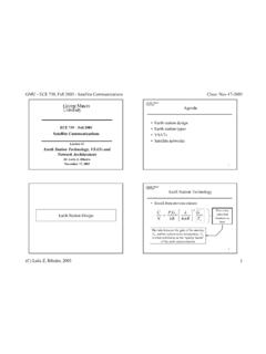
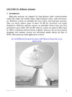
6 These pattern measurements are presented in either a rectangular or a polar format. The following figure shows a rectangular plot presentation of a typical 10 element Yagi. The detail is good but it is difficult to visualize the Antenna behavior at different Polar coordinate systems are used almost universally. In the polar-coordinate graph, points are located by projection along a rotating axis (radius) to an intersection with one of several concentric circles. Following is a polar plot of the same 10 element Yagi Antenna . Polar coordinate systems may be divided generally in two classes: linear and logarithmic. In the linear coordinate system, the concentric circles are equally spaced, and are graduated. Such a grid may be used to prepare a linear plot of the power contained in the signal. For ease of comparison, the equally spaced concentric circles may be replaced with appropriately placed circles representing the decibel response, referenced to 0 dB at the outer edge of the plot.
7 In this kind of plot the minor lobes are suppressed. Lobes with peaks more than 15 dB or so below the main lobe disappear because of their small size. This grid enhances plots in which the Antenna has a high directivity and small minor lobes. The voltage of the signal, rather than the power, can also be plotted on a linear coordinate system. In this case, too, the directivity is enhanced and the minor lobes suppressed, but not in the same degree as in the linear power the logarithmic polar coordinate system the concentric grid lines are spaced periodically according to the logarithm of the voltage in the signal. Different values may be used for the logarithmic constant of periodicity, and this choice will have an effect on the appearance of the plotted patterns. Generally the 0 dB reference for the outer edge of the chart is used. With this type of grid, lobes that are 30 or 40 dB below the main lobe are still distinguishable.
8 The spacing between points at 0 dB and at -3 dB is greater than the spacing between -20 dB and -23 dB, which is greater than the spacing between -50 dB and -53 dB. The spacing thus correspond to the relative significance of such changes in Antenna modified logarithmic scale emphasizes the shape of the major beam while compressing very low-level (>30 dB) sidelobes towards the center of the pattern. There are two kinds of radiation pattern: absolute and relative. Absolute radiation patterns are presented in absolute units of field strength or power. Relative radiation patterns are referenced in relative units of field strength or power. Most radiation pattern measurements are relative to the isotropic Antenna , and then the gain transfer method is then used to establish the absolute gain of the Antenna . The radiation pattern in the region close to the Antenna is not the same as the pattern at large distances. The term near-field refers to the field pattern that exists close to the Antenna , while the term far-field refers to the field pattern at large distances.
9 The far-field is also called the radiation 967field, and is what is most commonly of interest. Ordinarily, it is the radiated power that is of interest, and so Antenna patterns are usually measured in the far-field region. For pattern measurement it is important to choose a distance sufficiently large to be in the far-field, well out of the near-field. The minimum permissible distance depends on the dimensions of the Antenna in relation to the wavelength. The accepted formula for this distance is: rmin=2d2 where rmin is the minimum distance from the Antenna , d is the largest dimension of the Antenna , and is the Beamwidth An Antenna 's beamwidth is usually understood to mean the half-power beamwidth. The peak radiation intensity is found and then the points on either side of the peak which represent half the power of the peak intensity are located. The angular distance between the half power points is defined as the beamwidth.
10 Half the power expressed in decibels is 3dB, so the half power beamwidth is sometimes referred to as the 3dB beamwidth. Both horizontal and vertical beamwidths are usually that most of the radiated power is not divided into sidelobes, then the directive gain is inversely proportional to the beamwidth: as the beamwidth decreases, the directive gain Antenna is able to radiate all the energy in one preferred direction. Some is inevitably radiated in other directions. The peaks are referred to as sidelobes, commonly specified in dB down from the main NullsIn an Antenna radiation pattern, a null is a zone in which the effective radiated power is at a minimum. A null often has a narrow directivity angle 968compared to that of the main beam. Thus, the null is useful for several purposes, such as suppression of interfering signals in a given PolarizationPolarization is defined as the orientation of the electric field of an electromagnetic wave.