Transcription of Link Equation - KFUPM
1 link Equation In the past (about 10 years ago), you may have noticed that the TV satellite reflector antennas that were being used to receive TV channels from GEO satellites in the region were those usually black large reflector antennas with diameters in the range of 2 to 4 meters or so. Nowadays, you can receive TV stations from a satellite using much smaller antennas with diameters on the order of 1 meters or less. So, what caused this drop in size of reflector antennas? Did satellites suddenly start transmitting higher power that allow small reflectors to collect sufficient power now? The answer is NO.
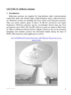
2 It has to do with the operating frequency. Aperture Antennas The term aperture antennas denotes all type of antennas that have an aperture (some form of an opening) such as horn antennas and reflector antennas. For these antennas, we can relate the different parameters of the antenna including the Gain of the antenna (G) and 3dB Beamwidth ( 3dB) to the specification of the antenna (size, diameter, ..) as follows: The 3dB Beamwidth ( 3dB): This is a measure of how spread the radiation of an antenna is. Considering the radiation pattern of an aperture antenna , the 3dB is a measure of the angle between the two directions around the antenna s boresight in which the radiated power drops to one half the maximum power that is radiated at the boresight direction.
3 The 3dB is given by: 3dB75D where is the wavelength (in meters) of the EM waves that the antenna is transmitting/receiving ( = c/f), and D is the diameter of the aperture in the direction at which the 3dB is measure. So, if the aperture of an antenna is not circular in shape, it may have two different values for the beamwidth in the vertical and horizontal directions. Gain (G): The gain, which is measure of the ability of an antenna to concentrate its power in a specific direction is given by the following relation: 24 AAG = where A is the aperture area.
4 A is the aperture efficiency representing how efficient is the aperture in collecting/reflecting the EM waves with lower values for smaller antennas and higher values for larger antennas, with typical values in the range of 55% - 70% for reflector antennas 65% - 90% for horn antennas. is the wavelength (in meters) of the EM waves that the antenna is transmitting/receiving ( = c/f), and When the aperture of an antenna is circular in shape with a diameter D, the gain becomes: 2 ADG = In terms of the 3dB beamwidth 3dB, the gain for a circular aperture antenna may be written as ()2355, 000 AdBG [The value of 3dB is in degrees in this formula] When the aperture is not circular with two different beamwidths in the horizontal direction (x-direction) and the vertical directions (y-direction), then the above formula for the gain becomes ()()
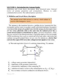
5 3355, 000 AdBdBXYG [The values of 3dB are in degrees in this formula] link Equation We often are interested in knowing how much power a receiving antenna will produced given that amount of power that the transmitting antenna transmits and the different parameters of the link including distance between antennas and transmission frequency. This relation is called the link Equation . To derive the link Equation , consider the following: 1. Consider an isotropic antenna that radiates an amount of power equal to tP Watts. Since this is an isotropic antenna , it radiates equal amount of power in all directions.
6 2. Consider an ideal receiving antenna that is in the form of a sphere with radius R that circulates around the transmitting antenna . Since this is a spherical antenna that encloses the transmitting antenna from all directions, it captures all the transmitted power, and therefore, the received power becomes rtPP=. 3. Now, assume that the receiving antenna is not a perfect antenna but has an efficiency A that is less than 1. Because of this, the received power becomes a fraction A of the transmitted power, or rAtPP = . 4. If the receiving antenna is not a complete sphere but only part of it with area A, then the receiving power becomes a fraction of the power received in (3) with the ratio being the ratio of the area of the receiving antenna A to the area of the sphere in (3) which is 24R.
7 This makes the received power become: 24 AtrPAPR = 5. The next step is to change the transmitting antenna from being an isotropic antenna to being a directional antenna with gain in the boresight direction of tG (assume the boresight direction of the transmitting antenna is adjusted such that it is pointing towards the receiving antenna , and that the receiving antenna is located in the far-field region of the transmitting antenna which certainly makes the size of the receiving antenna become negligible compared to the beamwidth of the transmitting antenna no matter how narrow it is).
8 In this case, the received power will increase by a factor of tG over the case when an isotropic antenna is used for transmission: 24 ATtrGPAPR = 6. We stated earlier that the gain of an antenna is 24 AAG = Re-writing this for the receiving antenna as follows: 24rAGA = Substituting for AA in the Equation obtained in (5) and re-arranging different quantities gives 24tt rrPGGPR = This is known as the link Equation . Important Notes: The quantity ttPG is called the Effective Isotropic Radiated Power (EIRP) and represents how much power would an isotropic antenna be required to transmit to have the same received power at the output of the receiving antenna .
9 Some reflector antennas with high extremely high gains may have an EIRP in the range of 1012 W. The quantity 24R is called the Path Loss pL. This represents the amount of drop in received power as the distance between the transmitting and receiving antennas increases. The link Equation can be summarized as EIRP Receiving antenna GainReceived Power=Path Loss It appears from the link Equation that decreasing the wavelength (increasing the frequency) without changing any other parameter results in decreasing the received power. However, this is not correct because the gains of the transmitting and receiving antennas also depend on the wavelength.
10 It can easily be shown that decreasing the wavelength (increasing the frequency) results in increasing the received power. Sometimes, it is more convenient to represent the link Equation in dB form where it becomes ()()() ()()()()()()21010 Receiving antenna GaindBWPath Loss dB4dBWdBWdBdB10 log4dBWdBdB20 logrt trtt rEIRPRPPGGRPG G =++ =++ In addition to the transmitted power in the numerator of the link Equation there are the gains of the transmitting and receiving antennas. In the denominator, there is the path loss. For a general form of the link Equation , sometimes additional losses that EM signals experience when transmitted from an Earth station to a satellite or vice versa are also added in the denominator.
