Transcription of LECTURE 19: Reflector Antennas Equation Section 19 1 ...
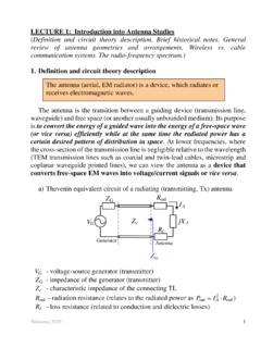
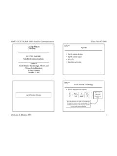
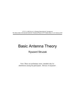
1 Nikolova 2010 1 LECTURE 19: Reflector Antennas Equation Section 19 1. Introduction High-gain Antennas are required for long-distance radio communications (radio-relay links and satellite links), high-resolution radars, radio-astronomy, etc. Reflector systems are probably the most widely used high-gain Antennas . They can easily achieve gains of above 30 dB for microwave and higher frequencies. Reflector Antennas operate on principles known long ago from geometrical optics (GO). The first RF Reflector system was made by Hertz back in 1888 (a cylindrical Reflector fed by a dipole). However, the art of accurately designing such antenna systems was developed mainly during the days of WW2 when numerous radar applications evolved. M INTELSAT EARTH STATION (ANT BOSCH TELECOM), DUAL Reflector Nikolova 2010 2 AIRCRAFT RADAR RADIO RELAY TOWER Nikolova 2010 3 FEED-HORN IS IN FOCAL POINT CONICAL HORN PRIMARY FEED Nikolova 2010 4 The simplest Reflector antenna consists of two components: a reflecting surface and a much smaller feed antenna , which often is located at the Reflector s focal point.
2 Constructions that are more complex involve a secondary Reflector (a subreflector) at the focal point, which is illuminated by a primary feed. These are called dual- Reflector Antennas . The most popular Reflector is the parabolic one. Other reflectors often met in practice are: the cylindrical Reflector , the corner Reflector , spherical Reflector , and others. 2. Principles of parabolic reflectors A paraboloidal surface is described by the Equation (see plot b) 24(),fFF za . ( ) Here, is the distance from a point A to the focal point O, where A is the projection of the point R on the Reflector surface onto the axis-orthogonal plane (the aperture plane) at the focal point. For a given displacement from the axis of the Reflector , the point R on the Reflector surface is a distance fr away from the focal point O.
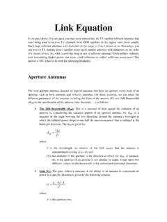
3 The position of R can be defined either by (, )fz , which is a rectangular pair of coordinates, or by (, )ffr , which is a polar pair Nikolova 2010 5of coordinates. A relation between (, )ffr and F is readily found from ( ): 221coscos( /2)fffFFr . ( ) Other relations to be used later are: 2sinsin2 tan1cos2fffffFrF . ( ) The axisymmetric (rotationally symmetric) paraboloidal Reflector is entirely defined by the respective parabolic line, , by two basic parameters: the diameter D and the focal length F (see plot b). Often, the parabola is specified in terms of D and the ratio F/D. When F/D approaches infinity, the Reflector becomes flat. Some parabolic curves are shown below.
4 When , the focal point lies in the plane passing through the Reflector s rim. F/D=1/3 F/D=1/2 Focal point 0 Nikolova 2010 6 The angle from the feed (focal) point to the Reflector s rim is related to /FD as 012arctan4( /)FD . ( ) The focal distance F of a given Reflector can be calculated after measuring its diameter D and its height 0H: 2016 DFH . ( ) Eq. ( ) is found by solving ( ) with /2D and 0fzFH . For example, if /1/4FD , then 00/4 HDHF , , the focal point is on the Reflector s rim plane. The Reflector design problem involves mainly the matching of the feed antenna pattern to the Reflector .
5 The usual goal is to have the feed pattern at about a 10 dB level in the direction of the rim, 0()10fF dB ( of the normalized amplitude pattern). The geometry of the paraboloidal Reflector has two valuable features: All rays leaving the focal point O are collimated along the Reflector s axis after reflection. All overall ray path lengths (from the focal point to the Reflector and on to the aperture plane) are the same and equal to 2F. The above properties are proven by the GO methods, therefore, they are true only if the following conditions hold: The radius of the curvature of the Reflector is large compared to the wavelength and the local region around each reflection point can be treated as planar. The radius of the curvature of the incoming wave from the feed is large and can be treated locally at the reflection point as a plane wave.
6 The Reflector is a perfect conductor, , 1 . The collimating property of the parabolic Reflector is easily established after finding the unit normal of the parabola, ppCC n. ( ) Nikolova 2010 7 Here, 2cos/ 20pffCFr ( ) is the parabolic curve Equation [see Equation ( )]. After applying the operator in spherical coordinates, pC is obtained as 2 coscossin222fffpffC r , ( ) and, therefore, cossin22ffff nr . ( ) The angles between n and the incident and reflected rays are found below: coscos2fif rn. ( ) According to Snell s law, ir.
7 It is easy to show that this is fulfilled only if the ray is reflected in the z-direction: cos(cossin)cossin22coscossinsincos .222ffrfffff ffffff znr r ( ) Thus, we proved that for any angle of incidence f the reflected wave is z-directed. The equal-path-length property follows from ( ). The total path-length L for a ray reflected at the point R is cos(1 cos)2fff ffLORRAr rrF . ( ) Notice that L is a constant equal to 2F regardless of the angle of incidence. Nikolova 2010 83. Aperture distribution analysis via GO (aperture integration) There are two basic techniques for the analysis of the radiation characteristics of reflectors. One is called the current distribution method, which is a physical optics (PO) approximation.
8 It assumes that the incident field from the feed is known, and that it excites surface currents on the Reflector s surface as 2is JnH. This current density is then integrated to yield the far-zone field. It is obvious that the PO method assumes that the Reflector has a perfectly conducting surface and makes use of image theory. Besides, it assumes that the incident wave coming from the primary feed is a locally plane far-zone field. With the aperture distribution method, the field is first found over a plane, which is normal to the Reflector s axis, and lies at its focal point (the antenna aperture). GO (ray tracing) is used to do that. Equivalent sources are formed over the aperture plane. It is assumed that the equivalent sources are zero outside the Reflector s aperture.
9 We first consider this method. The field distribution at the aperture of the Reflector antenna is necessary in order to calculate the far-field pattern, directivity, etc. Since all rays from the feed travel the same physical distance to the aperture, the aperture distribution is of uniform phase. However, there is a non-uniform amplitude distribution. This is because the power density of the rays leaving the feed falls off as 21/fr. After the reflection, there is practically no spreading loss since the rays are collimated (parallel). The aperture field-amplitude distribution varies as 1/fr. This is explained in detail below. Nikolova 2010 9 GO assumes that power density in free space follows straight paths. Applied to the power transmitted by the feed, the power in a conical wedge stays confined within as it progresses along the cone s axis.
10 Consider a conical wedge of solid angle d whose cross- Section angle is fd . It confines power, which after being reflected from the paraboloid, arrives at the aperture plane confined within a cylindrical ring of thickness d and area 2dAd . Let us assume that the feed is isotropic and it has radiation intensity /4tU , where t is the transmitted power. The power confined in the conical wedge is (/4)tdUdd . This power reaches the aperture plane with a density of ()4taddPdAdA . ( ) The generic relation between the solid angle increment and the directional-angle increments is sinddd , ( ) (see LECTURE 4).