Transcription of EI2400 Applied Antenna Theory Lecture 8: Reflector antennas
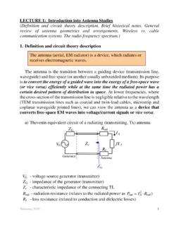
1 School of Electrical Engineering EI2400 Applied Antenna Theory Lecture 8: Reflector antennas Reflector antennas Reflectors are widely used in communications, radar and radio astronomy. The largest Reflector Antenna in the world is the radio telescope in Arecibo which has a spherical Reflector with a diameter of 300m. KTH School of Electrical Engineering 2. Parts of a Reflector Antenna Reflector antennas can have many different forms. Normally they consist of one or more reflectors which are designed to collimate an incident plane wave by reflection and transmission via each Reflector to a focal point at a convenient location. - The first Reflector on reception is the largest and is called the main Reflector . - The next Reflector is called the sub- Reflector . The feed Antenna is located in the focal point. - It is normally a horn Antenna or a dipole above a ground plane. KTH School of Electrical Engineering 3.
2 Sketch of a Reflector Antenna The parts of a Reflector Antenna : Feed Antenna Sub- Reflector If the sub- Reflector is: Feed Antenna -Convex: Cassegrain. -Concave: Gregorian. Main Reflector Main Reflector KTH School of Electrical Engineering 4. Radiation characteristics Reflector antennas ; W. Tang, , "Wideband Beam-Steerable Flat have often a fixed Reflectors via Transformation Optics," IEEE antennas and Wireless Propagation Letters, , 2011. main beam direction. However, they can also steered beams by mechanical displacement of the feed or by rotation and tilting of the whole Antenna . KTH School of Electrical Engineering 5. Radiation Normally, the radiation is aimed to be a plane wave. It is also possible to generate contoured beams, either by having one feed and shaping the Reflector , or by using a feed array, or both. KTH School of Electrical Engineering 6. Physical Optics (PO). jk ( z a z s ) 1. Formulation: Ea Er (rs )e Ha.
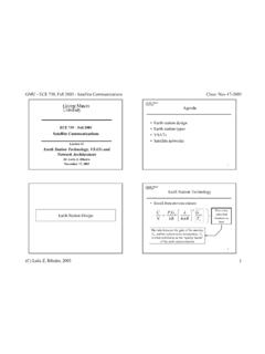
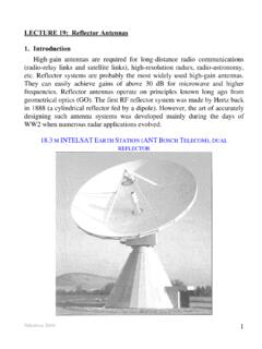
3 Z Ea Kildal, Foundations of antennas : A Unified Approach for Line-Of-Sight And Multipath , 2014. KTH School of Electrical Engineering 7. Parabola Parabola's properties: KTH School of Electrical Engineering 8. The paraboloidal Reflector (I). Our parabola is defined as follows: rs ( , ) z ( ) z 2. z( ) F . 4F. cos x sin y for 0 D / 2. rs ( f , ) rs ( f )r for 0 f 0. F 2F. r sin f cos f z r ( f ) . cos2 f / 2 1 cos f KTH School of Electrical Engineering 9. The paraboloidal Reflector (II). How to specify the parabola? - D and F. - D and 0. D 2 F tan 0 . - F and 0. 0 is fixed to the half beamwidth of the feed. KTH School of Electrical Engineering 10. Cassegrain Antenna The classical Cassegrain Antenna consists of a paraboloidal main Reflector and a hyperboloidal sub- Reflector . We need four independent parameters in order to uniquely describe the geometry of the Cassegrain: Kildal, Foundations of antennas : A Unified Approach for Line-Of-Sight And Multipath , 2014.
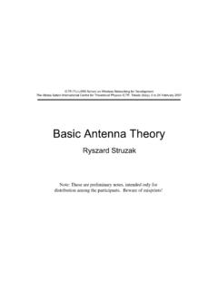
4 D, D, 0 and 0. KTH School of Electrical Engineering 11. Influence of the feed There is a compromise between directivity and efficiency (spillover). Blockage at the center. eap esp e pol eill e . Spillover efficiency. Polarization efficiency. Illumination efficiency. Phase efficiency. Kildal, Foundations of antennas : A Unified Approach for Line-Of-Sight And Multipath , 2014. KTH School of Electrical Engineering 12. Efficiencies (I). Spillover efficiency (esp): - This is the power within the subtended angle 0 ( , the power hitting the Reflector ) relative to the total power radiated by the feed. - This should be reduced as much as possible in order to improve the directivity. - The spillover efficiency is typically between dB. and dB, depending on the illumination taper of the aperture and the quality of the feed pattern. KTH School of Electrical Engineering 13. Efficiencies (II). Polarization efficiency (epol): - This is the power of the co-polar field relative to the total power, both within.
5 - In most Reflector antennas the polarization efficiency is very high, typically better than dB. Illumination efficiency (eill): - It measures the illumination taper of our feed. - Uniform illumination is the ideal case. - The illumination efficiency is in a practical Antenna typically between dB and dB, for illumination tapers varying between 10 dB and 20 dB. KTH School of Electrical Engineering 14. Efficiencies (III). Phase efficiency (e ): - The phase efficiency is the only sub-efficiency which depends on the location of the phase reference point of the feed, , the location of the feed relative to the focal point of the Reflector . - This fact can be used to uniquely define a phase center for the feed, corresponding to the feed location which maximizes the phase efficiency. - When the feed is located with its phase center in the focal point of the Reflector , the phase efficiency is normally very high, typically better than dB.
6 KTH School of Electrical Engineering 15. Aperture blockage In rotationally symmetric antennas the feed or the sub- Reflector and their support struts will cause aperture blockage. The center blockage can be accounted for in the efficiency calculations by a center blockage efficiency, Kildal, Foundations of antennas : A Unified which is obtained by Approach for Line-Of-Sight And Multipath , 2014. removing the central region from the aperture integral. KTH School of Electrical Engineering 16. Directivity It is coming from the side of our aperture and it is affected by the efficiencies: D D . 2 2. D0 eap esp e pol eill e .. - The effects of tolerances and the blockage caused by the feed and its support legs have not been included in this version of the efficiency. KTH School of Electrical Engineering 17. Edge diffraction efficiency The field incident on the main Reflector of the Cassegrain is reflected by GO.
7 From the sub- Reflector . GO is only valid when the reflectors are large in terms of wavelengths. - The finite diameter of the sub- Reflector will therefore cause edge diffraction losses. These diffractions will be more important when the Reflector (and sub- Reflector ) is small in terms of wavelength. KTH School of Electrical Engineering 18. Tailoring the radiation pattern The Reflector can be used to tailor the radiation pattern of our Antenna . Not only a directive pattern in one direction can be achieved. KTH School of Electrical Engineering 19. Reflect-arrays A planar version of a Reflector . - Advantages: Low cost. - Disadvantages: Narrow band. KTH School of Electrical Engineering 20.