Transcription of Introduction into the Antenna Studies - McMaster University
1 Nikolova 2020 1 lecture 1: Introduction into Antenna Studies (Definition and circuit theory description. Brief historical notes. General review of Antenna geometries and arrangements. Wireless vs. cable communication systems. The radio-frequency spectrum.) 1. Definition and circuit theory description The Antenna is the transition between a guiding device (transmission line, waveguide) and free space (or another usually unbounded medium). Its purpose is to convert the energy of a guided wave into the energy of a free-space wave (or vice versa) efficiently while at the same time the radiated power has a certain desired pattern of distribution in space. At lower frequencies, where the cross-section of the transmission line is negligible relative to the wavelength (TEM transmission lines such as coaxial and twin-lead cables, microstrip and coplanar waveguide printed lines), we can view the Antenna as a device that converts free-space EM waves into voltage/current signals or vice versa.
2 A) Thevenin equivalent circuit of a radiating (transmitting, Tx) Antenna LRradRAIAjXcZinZGVGZG eneratorAntenna GV - voltage-source generator (transmitter) GZ - impedance of the generator (transmitter) cZ - characteristic impedance of the connecting TL radR - radiation resistance (relates to the radiated power as 2radradAPIR= ) LR - loss resistance (related to conduction and dielectric losses) The Antenna (aerial, EM radiator) is a device, which radiates or receives electromagnetic waves. Nikolova 2020 2 AjX - Antenna reactance inZ - input impedance of feed network as seen from Antenna terminals rad()ALAZRRjX=+ + - Antenna impedance One of the most important tasks in Antenna design is the impedance matching of the Antenna to the transmission line (TL) and the generator in()AZZ =. Matching is often measured in terms of the voltage standing-wave ratio (VSWR or just SWR). Standing waves are avoided in high-power RF systems (radar, broadcasting) because they may cause arching or discharge in the TL.
3 But the main benefit of good impedance match (with low SWR) is the maximum power transfer to/from the Antenna . Minimizing conduction (metals) and polarization (dielectric) loss (represented by LR in Thevenin s equivalent) is also desirable. The losses decrease the efficiency of the Antenna . On the other hand, in special applications such as ultra-wideband (UWB) antennas in imaging and radar, the Antenna resistance may be increased intentionally in order to improve the bandwidth and suppress ringing in the transmitted or received signals. b) Thevenin equivalent circuit of a receiving (Rx) Antenna ReceiverAntennacZAZAIAVLZouZ ouZ - output impedance of the Antenna -plus-feed network, which serves as a signal generator as seen from the receiver terminals The Antenna is a critical component in a wireless communication system. A good design of the Antenna can relax the system requirements and improve its overall performance.
4 Nikolova 2020 3 2. Brief historical notes James Clerk Maxwell formulates the mathematical model of electromagnetism (classical electro-dynamics), A Treatise on Electricity and Magnetism , 1873. He shows that light is an electromagnetic (EM) wave, and that all EM waves propagate through space with the same speed, the speed of light. Heinrich Rudolph Hertz demonstrates in 1886 the first wireless EM wave system: a /2 -dipole is excited with a spark; it radiates predominantly at 8 m; a spark appears in the gap of a receiving loop some 20 m away. In 1890, he publishes his memoirs on electrodynamics, replacing all potentials by field strengths1. May 7, 1895, a telegraph communication link is demonstrated by the Russian scientist, Alexander Popov. A message is sent from a Russian Navy ship 30 miles out in sea, all the way to his lab in St. Petersburg, Russia. This accomplishment is little known today.
5 In 1892, Tesla delivers a presentation at the IRE of London about transmitting intelligence without wires, and, in 1895, he transmits signals detected 80 km away. His patent on wireless links precedes that of Marconi. Guglielmo Marconi sends signals over large distances and successfully commercializes wireless communication systems. In 1901, he performs the first transatlantic transmission from Poldhu in Cornwall, England, to Newfoundland, Canada. He receives the Nobel prize for his work in 1909. 1 Similar work on replacing the EM vector/scalar potentials with field vectors is done at about the same time by the English scientist Oliver Heaviside. Nikolova 2020 4 The beginning of 20th century (until WW2) marks the boom in wire- Antenna technology (dipoles and loops) and in wireless technology as a whole, which is largely due to the invention of the DeForest triode tube, used as a radio-frequency (RF) generator.
6 Radio links are realized up to UHF (about 500 MHz) and over thousands of kilometers. WW2 marks a new era in wireless communications and Antenna technology. The invention of new microwave generators (magnetrons and klystrons) leads to the development of the microwave antennas such as waveguide apertures, horns, reflectors, etc. It also marks the advent of radar detection and imaging. 3. General review of Antenna geometries and arrangements Single-element radiators A. Wire radiators (single-element) wire Antenna elementsstraight-wire elements(dipoles/monopoles)loopshelices There is a variety of shapes corresponding to each group. For example, loops can be circular, square, rhombic, etc. Wire antennas are simple to make but their dimensions are commensurable with a wavelength. This limits the frequency range of their applicability. At low frequencies, these antennas become increasingly large.
7 At very high frequencies, they are very small and the parasitics become difficult to control. Nikolova 2020 5 B. Aperture antennas (single element) (Q-par Angus) (a) pyramidal horn (b) conical horn (c) open rectangular waveguides Aperture antennas were developed before and during WW2 together with waveguide technology. Waveguides were primarily developed to transfer high-power microwave signals (cm wavelengths), generated by high-power sources such as magnetrons and klystrons. These types of antennas are preferable in the frequency range from 1 to 20 GHz. [Radiometer Physics Gmbh] Nikolova 2020 6 [Quinstar Technology Inc.] (d) double-ridge horns (TEM, linear polarization, ultra-wide band) [TMC Design Corp.] (e) quad-ridge horns (TEM, dual linear polarization allowing for many types of polarization depending on feed, ultra-wide band) [ZAX Millimeter Wave Corp.]
8 ] (f) corrugated horns (symmetric patterns, low side lobes, low cross-polarization), often used as primary feeds in reflector antennas Nikolova 2020 7 C. Printed antennas The patch antennas consist of a metallic pattern ( , a patch) etched on a dielectric substrate, which may have a grounded metallic plane at the opposite side. They have been first proposed in the beginning of 1970s. There is a great variety of geometries and ways of excitation. Modern integrated antennas often use multi-layer designs with a feed coupled to the radiator electromagnetically (no galvanic contact). PRINTED PATCH RADIATORS rectangular patch circular patch (c) printed dipole Nikolova 2020 8 (d) double-layer printed Yagi with microstrip feed Nikolova 2020 9 (e) printed monopole Antenna Various shapes used to form a radiating patch: Nikolova 2020 10 PRINTED SLOT RADIATORS (a) (b) (c) (d) (e) (f) (g) (h) Slot antennas were developed in the 1980s and there is still research on new shapes and types of excitation.
9 They are suited for integration with slot-line circuits, which are usually designed to operate at frequencies above 10 GHz. Popular slot Antenna in the microwave range is the Vivaldi slot (see a). Patch and slot antennas share some common features. They are easy and cheap to fabricate. They are easy to mount; they are light and mechanically robust. They have low cross-polarization radiation. Their directivity is not very high. They have relatively high conducting and dielectric losses. These radiators are widely used in patch/slot arrays, which are esp. convenient for use in spacecraft, satellites, missiles, cars and other mobile applications. Nikolova 2020 11 (i) UWB printed tapered slot (Vivaldi) Antenna (i) UWB printed antipodal Antenna with suppressed back-radiation Nikolova 2020 12 D. Leaky-wave antennas These are antennas derived from millimeter-wave (mm-wave) guides, such as dielectric guides, differential microstrip lines, coplanar and slot lines.
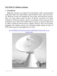
10 They are developed for applications at frequencies above 30 GHz, infrared frequencies included. Periodic discontinuities are introduced at the end of the guide leading to substantial radiation leakage (radiation from the dielectric surface). These are traveling-wave antennas. Dielectric-image guides with gratings Printed leaky-wave antennas Nikolova 2020 13 E. reflector antennas A reflector of a receiving Antenna is used to concentrate the EM energy in a focal point where the feed to the receiver is located. Astronomers have long used mirrors shaped as parabolic surfaces to transforms rays from a source in a focal point into a bundle of parallel rays. A parabolic-cylinder reflector was first used for radio waves by Heinrich Hertz in 1888. Reflectors are usually parabolic but spherical and corner reflectors are also used. reflector antennas have very high gain and directivity. Typical applications include radio telescopes, satellite communications and radars.