Transcription of ANTI-LOCK BRAKE SYSTEM - Stefan Caunter
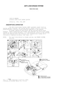
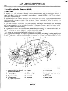
1 ANTI-LOCK BRAKE SYSTEM 1994 Volvo 960 1994 BRAKES Volvo BRAKE SYSTEM - ANTI-LOCK 960 DESCRIPTION ANTI-LOCK BRAKE SYSTEM (ABS) consists of speed sensors (onboth front rotors and in rear axle), an Electronic Control Unit (ECU)(under left side of instrument panel), and a hydraulic modulator (inengine compartment). See Fig. 1. The hydraulic modulator consists of front and rear pressurecontrol solenoids and relays, a return motor pump and relay, and anECU connector. Modulator pressure control solenoids are mounted insidehydraulic modulator and are not individually serviceable. Replacemodulator assembly if solenoids are defective. An ABS warning light in instrument panel will remainilluminated if an ABS failure occurs. If an ABS malfunction occurs,conventional braking SYSTEM takes over. Vehicle may be safely drivenwhen ABS warning light is : For more information on brakes, see BRAKE SYSTEM article in the BRAKES 1: Locating ABS ComponentsCourtesy of Volvo Cars of North America OPERATION Hydraulic SYSTEM consists of master cylinder, delivery lines,hydraulic modulator, electric solenoid valves, return delivery pumpand BRAKE calipers.
2 Solenoid valves are contained within hydraulicmodulator. Individual solenoid valves are used for pressure control toleft and right front calipers, while rear BRAKE line pressure iscontrolled by a common, regulated rear solenoid valve. Hydraulic modulator controls hydraulic pressure to each frontbrake caliper or both rear calipers independent of pressure producedby BRAKE master cylinder. However, pressure cannot exceed mastercylinder pressure. If wheel lock-up is sensed by speed sensors, ECU sends signalto hydraulic modulator. Hydraulic modulator operates electric returndelivery pump to reduce hydraulic pressure at BRAKE caliper(s). Thisis repeated until lock-up is eliminated. ABS SYSTEM has 2 relays (solenoid valve relay and pump motorrelay), mounted on top of hydraulic modulator. Battery voltage issupplied to relays through fuse panel. ECU supplies a ground forrelays when vehicle is in operation. This ECU-controlled groundsupplies voltage signal from solenoid valve relay to front-controlsolenoid and to rear-control solenoid.
3 Based upon speed sensorsignals, ECU controls solenoid operation by supplying ground toenergize individual solenoids. Return delivery pump motor relay closes when ground isprovided through control unit. Pressure relieved by solenoid valveoperation is returned to master cylinder by return delivery pump : See ANTI-LOCK BRAKE SAFETY PRECAUTIONS article in GENERAL INFORMATION section. BLEEDING BRAKE SYSTEMNOTE: Use only DOT 4 grade BRAKE fluid. 1) Fill BRAKE fluid reservoir to MAX level. Connect hoses toboth bleed valves on left rear wheel. Submerge hoses in bottlecontaining BRAKE fluid. Both hoses must be below BRAKE fluid surface. 2) Open bleed valves. Have an assistant slowly pump brakepedal 5 times, holding pedal down on last depression stroke. No airbubbles should be visible after last stroke. Close all bleeders. 3) Check BRAKE fluid level after each open-and-close cycle ofbleeders. Bleed remaining wheels in the following order: right rear,left front and right front.
4 ADJUSTMENTSNOTE: For adjustment information, see BRAKE SYSTEM article in the BRAKES section. TROUBLE SHOOTING ABS WARNING LIGHT ABS warning light on instrument cluster should go out afterstarting engine, indicating SYSTEM is okay. Individual components canbe tested with appropriate test equipment. See DIAGNOSIS & TESTING. DIAGNOSIS & TESTING PRE-DIAGNOSIS INSPECTION Perform a comprehensive visual inspection of systemcomponents before testing ABS SYSTEM to isolate simple failures. ABS REPAIR PRECAUTIONS Observe the following precautions when performing repairs: * Disconnect battery or electronic components with ignition switch in ON position. * Disconnect ECU connector when arc welding on vehicle. * NEVER subject ECU to temperatures greater than 180 F (82 C). * DO NOT Disconnect battery before charging with fast charger. DO NOT use fast charger to start : Test all ABS components and wiring before replacing ECU.
5 To prepare for testing, turn ignition switch to OFF cover from hydraulic modulator. Remove ECU connector bydepressing lock spring and swinging out connector. Leave ECU connectorunplugged, unless stated otherwise in testing procedure. Consultwiring diagram while performing tests. See WIRING DIAGRAMS in thisarticle. Check ECU connector terminals only through slots in side ofconnector. DO NOT use more force than necessary. Connector terminalnumbers are molded into side of connector. To reduce diagnostic time,test components in the following order. FUSES Check 10-amp transient surge protector fuse. Transient surgeprotector is clipped to ECU. See Fig. 1. ABS CIRCUIT TESTS Ground Circuits 1) Turn ignition off. Disconnect ECU connector. See Figs. 1and 2. Using DVOM, check resistance between ECU connector terminalsNo. 10, 20, 32 and 34 and ground. Resistance should be zero in : Never probe front of connectors. Check connectors only through slots in side of connector.
6 DO NOT use more force than necessary. See Fig. 2. 2) If resistance is not correct, check wiring harness betweenECU and ground connections. Terminals No. 10, 20, and 34 are groundedat left "A" pillar. If fault is found at terminal No. 32, retest withnew solenoid valve relay. See Fig. 2: Accessing ECU Connector Test SlotsCourtesy of Volvo Cars of North America Transient Surge Protector 1) Disconnect ECU connector. See Figs. 1 and 2. Turn ignitionon. Connect DVOM between terminal No. 1 on ECU connector and should read battery voltage. If battery voltage is not present,measure voltage on transient surge protector connector. Transientsurge protector is clipped to ECU. 2) Terminals No. 1, 2, and 4 should have battery for continuity between terminal No. 3 and ground. If onlyterminals No. 1 and 4 have voltage when terminal No. 3 is grounded,replace transient surge protector. ECU Power Circuits 1) Turn ignition on.
7 Disconnect ECU connector. See Figs. 1and 2. Connect negative lead of DVOM to ground. Check for voltage atterminal No. 25 (while depressing BRAKE pedal), and at terminals , 28 and 29 of ECU connector. All terminals should have batteryvoltage except for terminal No. 29, which should have . volt. 2) If no voltage is present at the following terminals,perform appropriate repair: * No. 25 - Check brakelight switch. Replace if defective. * No. 27 - Replace defective solenoid valve relay. * No. 28 - Replace defective pump motor relay. * No. 29 - If voltage reading at terminal No. 27 is correct, voltage at terminal No. 29 should be . volt. If voltage at terminal No. 29 is not correct, replace solenoid relay. Hydraulic Modulator Power Circuits 1) Turn ignition off. Disconnect hydraulic modulatorconnector. Turn ignition on. 2) Connect DVOM negative lead to ground and positive lead tohydraulic modulator connector terminals No.
8 6, 7, 10 and 12. DVOM should indicate battery voltage. If battery voltage is not present,perform the following repairs: * No. 6 - Check wire harness and fuses. * No. 7 - Attach connector to hydraulic modulator. ABS warning light should illuminate. If light does not illuminate, replace bulb. * No. 10 - Check transient surge protector fuse. If fuse is okay, replace transient surge protector. * No. 12 - Check wire harness and 80-amp fuse on top of right front wheelwell. 3) Turn ignition switch off. Attach connector to modulator. SENSORS Front Speed Sensors 1) Disconnect ECU connector. See Figs. 1 and 2. Using DVOM,check resistance between ECU connector terminals No. 4 and 6 (leftsensor). Check resistance between ECU connector terminals No. 11 and21 (right sensor). Resistance should vary from 900-2200 ohms as wheelis rotated. 2) If resistance is not within specification, checkresistance at sensor connectors on suspension tower in enginecompartment.
9 If resistance is within specification, repair wiringharness to ECU. If resistance is not within specification, replacesensor. See Fig. 3. 3) Check pulse wheels for damage. Maximum radial run-out is .006" (.15 mm).Fig. 3: Locating ABS Front Speed SensorCourtesy of Volvo Cars of North America Rear (Axle) Speed Sensor 1) Disconnect ECU connector. See Figs. 1 and 2. Connect DVOM between ECU connector terminals No. 7 and 9. Resistance should varyfrom 600-1600 ohms as rear wheels are rotated. 2) If resistance is not within specification, check sensorresistance at sensor connector at fuel filler pipe in trunk. Ifresistance is within specification, repair wiring harness to ECU. Ifresistance is not within specification, replace sensor. See Fig. 4. 3) On vehicles without multi-link axle, if gap between sensorand pulse wheel is greater than .007" (.2 mm) or has damaged teeth,sensor gives incorrect signals and must be 4: Locating ABS Rear Speed SensorCourtesy of Volvo Cars of North America SOLENOIDS Hydraulic Modulator 1) Turn ignition off.
10 Disconnect ECU connector. See Figs. 1and 2. Connect DVOM between ECU connector terminals No. 32 and 2 tocheck left front control solenoid. Connect DVOM between ECU connectorterminals No. 18 (rear control solenoid) and No. 35 (right frontcontrol solenoid). Resistance should be . ohms. 2) If resistance is not within specification, unplughydraulic modulator connector. Test resistance between hydraulicmodulator terminal No. 4 (ground) and hydraulic modulator terminalsNo. 1, 3, and 5. If readings are within specification, repair ECUwiring harness to modulator. If readings are not within specification,replace hydraulic modulator. See HYDRAULIC MODULATOR under REMOVAL &INSTALLATION. RELAYS Return Pump Motor Relay 1) Disconnect ECU connector. See Figs. 1 and 2. Turn ignitionon. Connect jumper wire between ECU connector terminal No. 28 : Relay should not remain grounded for more than 2 seconds, or damage to relay may occur. 2) Simultaneously measure voltage across connector terminalNo.