Transcription of ANTI-LOCK BRAKE SYSTEM - PDF.TEXTFILES.COM
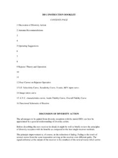
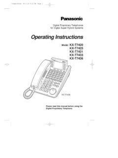
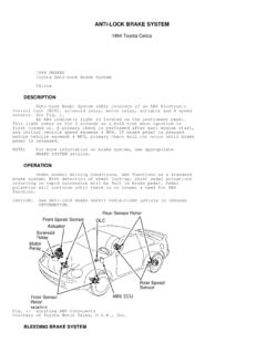
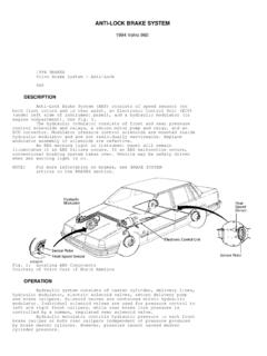
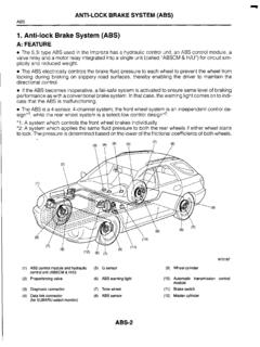
1 ANTI-LOCK BRAKE SYSTEM 1992 Infiniti G20 1990-92 BRAKES Infiniti ANTI-LOCK BRAKE SYSTEM Infiniti; G20, M30, Q45 DESCRIPTION & OPERATION The ANTI-LOCK BRAKE SYSTEM (ABS) prevents wheel lock-upduring abrupt braking. The SYSTEM detects wheel rotation rate andelectronically controls fluid pressure applied to the brakes. A slight vibration and noise may be noticed during hardbraking. These conditions are normal and indicate the ANTI-LOCK brakesystem is functioning properly. If a malfunction occurs in the SYSTEM , ANTI-LOCK feature will not function but conventional brakes willcontinue to operate normally. See Figs. : For more information on BRAKE SYSTEM , see BRAKE SYSTEM 1: ABS Component Locations (G20)Courtesy of Nissan Motor Co., 2: ABS Wiring Schematic (G20)Courtesy of Nissan Motor Co., 3: ABS Control Unit Connectors(G20)Courtesy of Nissan Motor Co., 4: ABS Component Locations (M30)Courtesy of Nissan Motor Co.
2 , 5: ABS Wiring Schematic (M30)Courtesy of Nissan Motor Co., 6: ABS Control Unit Connectors(M30)Courtesy of Nissan Motor Co., 7: ABS Component Locations & Wiring Schematic (Q45)Courtesy of Nissan Motor Co., 8: ABS Wiring Schematic (Q45)Courtesy of Nissan Motor Co., 9: ABS Control Unit Connectors(Q45)Courtesy of Nissan Motor Co., SERVICING CHECKING BRAKE FLUID LEVEL Fluid level should be between maximum and minimum lines onmaster cylinder reservoir. If fluid level is extremely low, checkbrake SYSTEM for leaks. When BRAKE warning light comes on (parkingbrake lever released), check BRAKE SYSTEM for leaks. Use DOT 3 brakefluid to replenish reservoir. ANTI-LOCK BRAKE SAFETY PRECAUTIONS * NEVER open a bleeder valve or loosen a hydraulic line while ABS is pressurized * NEVER disconnect or reconnect any electrical connectors while ignition is on. Damage to ABS control unit may result.
3 * DO NOT attempt to bleed hydraulic SYSTEM without first referring to the appropriate article. * Only use specially designed BRAKE hoses/lines on ABS-equipped vehicles. * DO NOT tap on speed sensor components (sensor, sensor rings). Speed rings must be pressed, NOT hammered into hubs. Striking these components can cause demagnetization or a loss of polarization, affecting the accuracy of the speed signal returning to the ABS control unit. * DO NOT mix tire sizes. Increasing the width, as long as tires remain close to the original diameter, is acceptable. Rolling diameter must be identical for all 4 tires. Some manufacturers recommend tires of the same brand, style and type. Failure to follow this precaution may cause inaccurate wheel speed readings. * DO NOT contaminate speed sensor components with grease. Only use recommended anti -corrosion coating.
4 * When speed sensor components have been removed, ALWAYS check sensor-to-ring air gaps when applicable. These specifications can be found in each appropriate article. * ONLY use recommended BRAKE fluids. DO NOT use silicone BRAKE fluids in an ABS-equipped vehicle. * When installing transmitting devices (CB s, telephones, etc.) on ABS-equipped vehicles, DO NOT locate the antenna near the ABS control unit (or any control unit). * Disconnect all on-board computers, when using electric welding equipment. * DO NOT expose the ABS control unit to prolonged periods of high heat (185 F/85 C for 2 hours is generally considered a maximum limit). BLEEDING BRAKE SYSTEM BRAKELINE BLEEDING 1) Carefully monitor BRAKE fluid level at master cylinderduring bleeding operation. Fill reservoir with DOT 3 BRAKE reservoir is full at all times while bleeding air out ofsystem.
5 Bleed brakes in sequence. See BRAKELINE BLEEDING SEQUENCE table. 2) Connect a transparent vinyl tube to air bleeder depress BRAKE pedal several times. With BRAKE pedal depressed,open air bleeder valve to release air. Close air bleeder BRAKE pedal slowly. Repeat procedure until clear BRAKE fluidcomes out of air bleeder BLEEDING SEQUENCE TABLE Application SequenceG20 .. LR, RF, RR, LFM30 & Q45 .. LR, RR, LF, RF, Front ABS Actuator, Rear ABS Actuator REMOVAL & INSTALLATION ACTUATOR Removal & Installation Disconnect negative battery cable. Drain BRAKE fluid frombrakelines. Mark brakelines for installation reference. Disconnectwiring harness and brakelines. Remove 3 actuator mounting nuts. Toinstall, connect brakelines without tightening. Install and tightenactuator mounting nuts. Tighten brakelines. See TORQUE SPECIFICATIONS table under TORQUE SPECIFICATIONS.
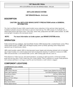
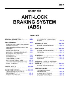
6 After installation, add BRAKE fluidand bleed brakelines. See BLEEDING BRAKE SYSTEM . FRONT/REAR WHEEL SENSORS Removal & Installation Removal and installation procedures are not available. Useillustration for guide. See Fig. 10, 11 or 12. DO NOT damage sensoredge and sensor rotor 10: Locating Front/Rear ABS Sensor (G20)Courtesy of Nissan Motor Co., 11: Removing & Installing Front/Rear ABS Sensor (M30)Courtesy of Nissan Motor Co., 12: Removing & Installing Front/Rear ABS Sensor (Q45)Courtesy of Nissan Motor Co., TORQUE SPECIFICATIONSTORQUE SPECIFICATIONS TABLE Application Ft. Lbs. ( )Brakeline Flare Nuts .. 11-13 (15-18)Companion Flange Nut (M30) .. 137-159 (186-216)Drive Pinion Nut (Q45) .. 137-217 (186-294)Rear Sensor Mounting Nut (Q45) .. 13-20 (18-26) INCH Lbs. ( )Actuator Mounting Nuts .. 96-144 (11-16)Front Harness Retainer Nut (M30).
7 ( )Front Sensor Bracket (M30) .. 71-96 (8-11)Front Sensor Mounting Nut G20 .. 96-132 (11-15) M30 & Q45 .. 96-144 (11-16)Rear Harness Retainer Nut (Q45) .. ( )Rear Sensor Mounting Nut (G20) .. 96-132 (11-15)Rear Sensor-To-Axle Tube .. 71-96 (8-11) DIAGNOSIS & TESTING PRELIMINARY CHECKSNOTE: Before starting ABS SYSTEM checks, road test vehicle to confirm customer complaint. Preliminary Check No. 1 Ensure BRAKE fluid level is correct. Add fluid if mechanical condition of conventional BRAKE SYSTEM , includingbrake booster and component adjustments. See DISC article. Repair oradjust BRAKE SYSTEM as necessary. Preliminary Check No. 2 Check wheel sensor clearance. See WHEEL SENSOR CLEARANCE table. Check rear sensor rotor (trigger wheel) teeth for damage. Checkfor dust, foreign materials and/or improper installation. Ifnecessary, replace sensor rotor with wheel hub or companion flange asa SENSOR CLEARANCE TABLE Application In.
8 (mm)G20 .. ( )M30 .. ( )Q45 Front .. (. ) Rear .. (. ) Preliminary Check No. 3 Measure each wheel sensor resistance. Resistance should be800-1200 ohms. If resistance is not as specified, replace sensor(s). Preliminary Check No. 4 1) Check ANTI-LOCK warning light for proper operation whenignition is turned on. If light does not glow, check ABS fuse andbulb. 2) If light glows, start engine. If light goes out, go tonext step. If light does not go out, keep engine running. On M30,locate ABS control unit in trunk (on rear shelf, next to speakers).See Fig. 4. On G20 and Q45, ABS control unit is under right side ofdash (behind glove box). See Fig. 1 or 7. On all models, count numberof LED flashes during 5-10 second OFF period and then go to SELF-DIAGNOSIS. 3) Road test vehicle at least one minute at speed greaterthan 19 MPH (30 km/h). If ANTI-LOCK warning light remains off and ABSoperation is abnormal, perform PRELIMINARY CHECK NO.
9 2. If light comeson, go to next step. 4) Keep engine running. Observe LED on ABS control number of LED flashes during 5-10 second OFF period and then goto SELF-DIAGNOSIS. SELF-DIAGNOSIS 1) When a problem occurs in ANTI-LOCK BRAKE SYSTEM , warninglight on instrument cluster comes on. To obtain satisfactory self-diagnostic results, always road test vehicle at least one minute atspeed greater than 19 MPH (30 km/h). 2) Stop vehicle, but keep engine running. On M30, locate ABScontrol unit in trunk (on rear shelf, next to speakers). See Fig. G20 and Q45, ABS control unit is under right side of dash (behindglove box). See Fig. 1 or 7. Count number of LED flashes during 5-10second period, and go to appropriate SELF-DIAGNOSTICS CHART. SeeFig. 7 or 8. If more than 2 circuits malfunction at same time, LEDwill display only one malfunction. After circuit has been repaired,LED will then display any remaining SYSTEM malfunctions.
10 3) Turn ignition off after repairs. Road test vehicle toverify malfunction has been corrected. If ignition is not turned off,warning light and LED will continue to indicate problem exists eventhough malfunction has been repaired. DIAGNOSING BY SYMPTOMS To diagnose ANTI-LOCK BRAKE SYSTEM (ABS) by symptom, refer toappropriate SYMPTOM CHART. See Fig. 13 or 15. Chart will indicateproper procedures to follow based on symptom : For diagnostic procedures, see appropriate DIAGNOSTIC PROCEDURES CHARTS. For preliminary check procedures, see PRELIMINARY 13: ABS Symptom Charts (G20)Courtesy of Nissan Motor Co., SELF-DIAGNOSTICS CHARTSELF-DIAGNOSTICS CHART (G20) No. Of Malfunctioning DiagnosticLED Flashes Part Or Unit Procedure .. Left Front Actuator Solenoid Circuit .. 72 .. Right Front Actuator Solenoid Circuit .. 73 .. Right Rear Actuator Solenoid Circuit.