Transcription of GROUP 35B ANTI-LOCK BRAKING SYSTEM (ABS) - …
1 35B-1 GROUP 35 BANTI-LOCK BRAKING SYSTEM (ABS)CONTENTSGENERAL DESCRIPTION..35B-2 ABS DIAGNOSIS ..35B-4 INTRODUCTION TO ANTI-LOCK BRAKING SYSTEM DIAGNOSIS .. 35B-4 ABS DIAGNOSTIC TROUBLESHOOTING STRATEGY.. 35B-4 DIAGNOSIS FUNCTION.. 35B-5 DIAGNOSTIC TROUBLE CODE CHART .. 35B-11 DIAGNOSTIC TROUBLE CODE PROCEDURES.. 35B-12 SYMPTOM CHART.. 35B-62 SYMPTOM PROCEDURES .. 35B-63 DATA LIST REFERENCE TABLE .. 35B-101 ACTUATOR TEST REFERENCE TABLE.. 35B-102 CHECK AT ABS-ECU .. 35B-102 SPECIAL TOOLS..35B-105ON-VEHICLE SERVICE..35B-106 ABS SENSOR OUTPUT VOLTAGE MEASUREMENT .. 35B-106 HYDRAULIC UNIT CHECK.
2 35B-108IN THE EVENT OF A DISCHARGED BATTERY .. 35B-110 HYDRAULIC UNIT ..35B-111 REMOVAL AND INSTALLATION .. 35B-111 ABS SENSOR..35B-113 REMOVAL AND INSTALLATION .. 35B-113 INSPECTION.. 35B-114G-SENSOR ..35B-115 REMOVAL AND INSTALLATION .. 35B-115 INSPECTION.. 35B-116 STEERING ANGULAR VELOCITY SENSOR ..35B-117 REMOVAL AND INSTALLATION .. 35B-117 SPECIFICATIONS ..35B-118 FASTENER TIGHTENING SPECIFICATIONS.. 35B-118 GENERAL SPECIFICATIONS .. 35B-118 SERVICE SPECIFICATIONS .. 35B-118 GENERAL DESCRIPTIONTSB RevisionANTI-LOCK BRAKING SYSTEM (ABS)35B-2 GENERAL DESCRIPTIONM1352000100681 Top components such as Brembo brakes, EBD and sports ABS improve BRAKING power and BRAKING ABS 4-wheel independent control optimizes the brake force to each wheel to achieve a balance of improved BRAKING force and BRAKING stability.
3 A steering angular velocity sensor was added to monitor the steering angle status. BRAKING force is altered in response to the steering status to improve the quality of steering when cornering. The steering angular velocity sensor, lateral G-sensor and longitudinal G-sensor accurately monitor driving conditions and optimize ABS con-trol to match the specific driving (ELECTRONIC brake -FORCE DISTRIBUTION SYSTEM ) Rear brake power is electronically controlled to optimize performance in accordance with road and load conditions and to ensure optimal distri-bution of BRAKING force between the front and rear brakes.
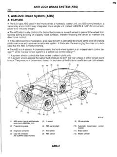
4 Rear brake fluid pressure control employs a brake modulator hydraulic unit solenoid valve that made it possible to eliminate the pressure control valves (proportioning valves). Effective use of rear wheel brake force reduces temperature build-up in the front brakes under hard BRAKING conditions. Independent control of the left and right rear brakes when BRAKING during cornering achieves a balance of improved vehicle stability and BRAKING DIAGRAM10067 AUAC211546AC209828AB113524697, 108 NAME OF OF FUNCTIONS ensorABS sensor1 Sends alternating current signals at frequencies which are proportional to the rotation speeds of each wheel to the G-sensor2 Sends data on vehicle s rate of lateral acceleration to the G-sensor3 Sends data on vehicle s rate of longitudinal acceleration to the angular velocity sensor4 Sends data on steering wheel angle to the the ABS-ECU when steering wheel is in straight-ahead switch5 Sends a signal to the ABS-ECU to indicate whether the brake pedal is depressed or brake switch6 Sends a signal to the ABS-ECU to indicate
5 Whether the parking brake lever is pulled or unit7 Drives the solenoid valves according to signals from the ABS-ECU in order to control the brake hydraulic pressure for each warning light8 Illuminates in response to signals from the ABS-ECU when a problem develops in the link connector9 Outputs the diagnostic trouble codes and allows communication with the scan modulator (ABS-ECU)10 Controls actuators (described above) based on the signals coming from each the self-diagnosis and fail-safe the diagnostic function (scan tool compatible).GENERAL DESCRIPTIONTSB RevisionANTI-LOCK BRAKING SYSTEM (ABS) CHECK SOUNDWhen starting the engine, a thudding sound can sometimes be heard coming from the engine com-partment.
6 This is a normal sound during the ABS OPERATION SOUNDS AND SENSATIONSD uring normal operation, the ABS makes several sounds that may seem unusual at first: A whining sound is caused by the ABS hydraulic unit motor. When pressure is applied to the brake pedal, the pulsation of the pedal causes a scraping sound. When the brakes are applied firmly, the ABS operates, rapidly applying and releasing the brakes many times per second. This repeated application and release of BRAKING forces can cause the suspension to make a thumping sound and the tires to STOPPING DISTANCES ON LOOSE ROAD SURFACESWhen BRAKING on loose surfaces like snow-covered or gravel roads, the stopping distance can be longer for an ABS-equipped vehicle than the stopping dis-tance for a vehicle with a conventional brake AT STARTING CHECKS hock may be felt when the brake pedal is lightly pressed while driving at a low speed.
7 This is a nor-mal characteristic because the ABS SYSTEM opera-tion check is carried out when vehicle speed is 8 km/h (5 mph) or DIAGNOSISTSB RevisionANTI-LOCK BRAKING SYSTEM (ABS)35B-4 ABS DIAGNOSISINTRODUCTION TO ANTI-LOCK BRAKING SYSTEM DIAGNOSISM1352012500482 The ANTI-LOCK brake SYSTEM (ABS) operates differ-ently from conventional brake systems. These differ-ences include sounds, sensations, and vehicle performance that owners and service technicians who are not familiar with ABS may not be used operational characteristics may seem to be malfunctions, but they are simply signs of normal ABS operation.
8 When diagnosing the ABS SYSTEM , keep these operational characteristics in mind. Inform the owner of the kind of performance charac-teristics to expect from an ABS-equipped DIAGNOSTIC TROUBLE CODE DETECTION CONDITIONSABS diagnostic trouble codes (ABS DTCs) are set under different conditions, depending on the mal-function detected. Most ABS DTCs will only be set during vehicle operation. Some ABS DTCs will also be set during the ABS self-check immediately after the engine is you check if an ABS DTC will be displayed again after the DTC has been erased, you should duplicate the ABS DTC set conditions.
9 Depending on the detection timing and set conditions for the spe-cific ABS DTC, you must either drive the vehicle or turn the engine off and restart it. To set the proper conditions for that DTC again, refer to "ABS DTC SET CONDITIONS" for each ABS DTC that you are trying to DIAGNOSTIC TROUBLESHOOTING STRATEGYM1352011100782 Use these steps to plan your diagnostic strategy. If you follow them carefully, you will be sure that you have exhausted most of the possible ways to find an ABS Gather information about the problem from the Verify that the condition described by the customer Check the vehicle for any ABS If you cannot verify the condition and there are no ABS DTCs, the malfunction is intermittent.
10 Refer to GROUP 00, How to use Troubleshooting/Inspection Service Points How to Cope with Intermittent Malfunctions If you can verify the condition but there are no ABS DTCs, or the SYSTEM cannot communicate with the scan tool, check that the basic brake SYSTEM is operating properly. If the basic brake SYSTEM is not operating prop-erly, refer to the GROUP 35A, Basic brake Sys-tem Diagnosis If the basic brake SYSTEM is operating properly, refer to If there is an ABS DTC, record the number of the DTC, then erase the DTC from the memory using the scan Reproduce the ABS DTC set conditions to see if the same ABS DTC will set again.