Transcription of OPERATIONAL CONCEPT AND PROCEDURES FOR …
1 OPERATIONAL CONCEPT AND. PROCEDURES FOR HF RADIO IN. THE BRIGADE COMBAT TEAMS. PREPARED BY DAVID M. FIEDLER 732-532-3760. ELECTRONICS ENGINEER. OPM -TRCS. FORT MONMOUTH NJ 07703. TRANSFORMATION high frequency (HF) RADIO SYSTEM (THFRS) - AN/PRC-150 FAMILY STANDARD OPERATING PROCEDURE (SOP) AND. OPERATIONS CONCEPT (OC) FOR THE BRIGADE COMBAT TEAMS. PURPOSE: This SOP/OC is intended to describe the planning factors and OPERATIONAL PROCEDURES required to successfully use THFRS radios in the Brigade Combat Team (BCT). WHY HF RADIO FOR THE BCT: HF radio (radio signals in the frequency spectrum). have the following characteristics that makes it an ideal communications system to support the fast moving wide area operations that the Brigade Combat Team will participate in: I - HF signals travel longer distances over the ground than the higher frequency VHF.
2 (SINCGARS) or UHF (EPLRS/NTDR) signals do because they are less affected by factors such as terrain or vegetation. 2 - HF signals can be reflected off the ionosphere (a layer of charged gases surrounding the earth at high altitudes) in a way that will cover beyond line of sight (BLOS) areas at distances out to 400 miles without gaps in communications coverage. 3 - HF signals can be reflected off the ionosphere to cover distances of many thousands of miles for "reach back" communications. 4 - HF signals do NOT require the use of either SATCOM or retransmission (RETRANS) assets. 5 - HF equipment provided to the Brigade can be used either fixed station or on the move (OTM). 6 - HF systems can be engineered to operate independent of intervening terrain or mamnade obstructions.
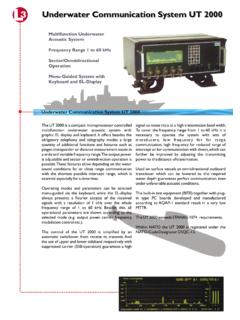
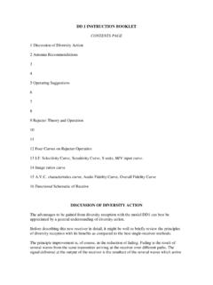
3 HF (2-3 OMhz) RADIO WAVE PROPAGATION: Radio propagation is the process by which electromagnetic energy (signal) moves from one point to another. Since radio waves propagate (move). the same way light waves do for this SOP/OC we can think of radio waves in terms of light. As with light rays, radio energy (signal) can travel from a point source outward in all directions just as a light spreads from a light bulb. For radio waves this is called an omni-directional signal. Figure 1 shows how radio energy (signal) decreases as distance from the source increases. Note that as the distance (range) doubles the signal strength is reduced to one quarter of what it was (proportional to I/d squared). Also as with light, radio signals can be focused to travel in a single direction similar to a flashlight beam.
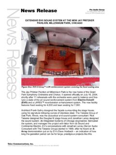
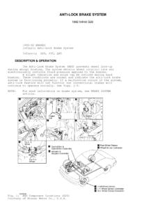
4 This is called a directional signal. The shaping of the radio signal is a function of the radios antenna system. Just as with light, radio signals can also be blocked by obstructions and bent (diffracted) over solid obstructions. This is similar to seeing the small amount of light that can be detected from a source behind a wall. All of these effects will be used to provide gap free tactical HF. radio communications throughout the Brigades area of operations and back to its sustaining base. It is important to recognize that how the radio antenna shapes the signal pattern and the system operating radio frequency (s) are the two most critical factors in assuring HF communications for the Brigade. POSSIBLE TRANSMISSION PATHS WITHIN THE BRIGADE OPERATIONAL AREA: Fig 2 shows possible radio paths between two stations located in the Brigade area of operations.
5 It is assumed that most combat units in the Brigade will be located within a maximum distance of 400 miles from each other for purposes of this SOP/OC. Circuits of greater distances (reach back) will be covered under other sections of this SOP/OC. Fig 2 shows three possible low angle radio paths located along or near the surface of the earth. These paths are called ground-wave paths because they are close to the earth's surface or in contact with it. They consist of the (1) direct wave path. The direct wave consists of radio frequency energy that travels through the atmosphere and near the earth directly from one antenna to another. This is called the line of sight (LOS) mode of propagation. Maximum LOS distance depends upon the height of the antenna above the ground and whether or not the path is obstructed by terrain that will block radio signals.
6 On flat ground, direct wave paths suitable for THFRS communications can be expected out to 6-8 miles before the curve of the earth blocks the signals. Direct wave communications can go much further if stations are located high on hilltops with no intervening obstructions so control of high ground and antenna height is important when using direct wave communications. (2) The ground reflected path like the direct path travels through the atmosphere but due to the lower "take off' angles from the transmitting antenna, the signal energy is reflected off the earth while traveling from the transmitting antenna to the receiving antenna. Depending upon the composition of the ground at the reflecting point the reflected energy can be considerably reduced when it arrives at the receiving antenna.
7 Signals reflected off seawater lose almost no energy while signals reflected off a sandy desert become quite weak. When summed together the direct wave and the reflected wave are referred to as the space wave. As the two combine, they can result in either a stronger or weaker total signal depending upon the timing difference of the two signals as they arrive. The difference in signal phasing is caused by the longer distance traveled by reflected wave. Space wave signals will usually not be the predominate mode of communications in the BCT. The (3) surface wave path is the transmitted radio energy that travels along the boundary between the atmosphere and the earth's surface and is in actual contact with the earth's surface. The surface wave is greatly affected by the electrical conductivity of the earth in the path of propagation.
8 With a good conductor such as seawater surface wave communications out to 1 00+ miles are possible. With a poor surface such as sand or frozen ground surface wave communications are greatly reduced. Surface wave signals are also greatly reduced by heavy vegetation or mountainous terrain. Surface wave signals can be made stronger over poor ground by using techniques that improve the conductivity of the earth near the antenna. Most HF ground-wave communications within the BCT will utilize surface wave signals. Space wave communications will predominate only when communicating from high ground to other high ground locations along the line of sight (LOS). Vertical monopole (whip) man-pack and vehicle antennas of various lengths are the antennas provided to produce the low take off angle energy needed to generate ground wave signals.
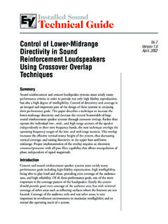
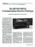
9 Figure 3 shows the antenna energy pattern of the vertical monopole (whip) antenna. Note that the signal is along the surface of the earth and on the lower angles. There is much less energy on the higher angles and none directly overhead (vertical angles). The pattern resembles a doughnut so operationally, it can be very difficult to communicate with aircraft that are directly overhead while you can talk to aircraft many miles away that are receiving low angle energy from a vertical antenna. THE IONOSPHERE: The ionosphere is an electrically charged region of atmospheric gases that surround the Earth. Ionization (electric charge) happens when solar radiation bombards atmospheric gas molecules and forces them to detach electrons leaving the gas molecule with a positive electrical charge called an ion and leaving free electrons in the atmosphere.
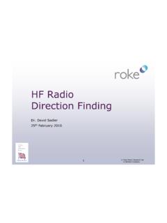
10 Since positive electrical charges repel each other the gas ions tend to "bunch" in distinct "layers" of ions at heights of between 30 and 300 miles shown in fig 4. These charged areas will reflect radio signals back to earth if they strike the ionosphere at particular angles using particular frequency bands. Radio engineers have labeled these layers the D, E, F I. and F2 layers (see fig 4). 3 factors determine whether a radio signal will be reflected back to earth and can be used by Brigade THFRS communications systems. They are (1) the higher the radio frequency the more likely the signal will penetrate the ionosphere rather than be reflected by it, (2) the current ion density determined by the amount of sun light (time of day, season, solar activity) at the time communications is desired, and (3) the angle at which the radio wave contacts the ionosphere.