Transcription of Antriebstechnik Operating Instructions - Lenze
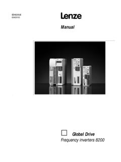
1 EDB2130IB/GB00381616 LAntriebstechnikOperating InstructionsPROFIBUS-FMS/DPBus interface moduleType 2130 IBThese Operating Instructions are valid for the interface modules as of nameplate V001 PROFIBUS-FMS/DPwith V002 PROFIBUS-FMS/DP withoptical fibre cabletogether with the controller series as calculatorController typeDesignHardware version + indexSoftware version + indexVariantExplanationImportant:These Operating Instructions are only valid together with theoperating Instructions of the suitable controllers or automationmodules!corresponds to the German edition of 15 February, 1995revisedEdition of to use these locate information on specific topics, simply refer to the table ofcontents at the beginning and to the index at the end of the Operating Instructions use a series of different symbols toprovide quick reference and to highlight important symbol refers to items of information intended to which should be observed to avoid possible damage to ordestruction of which should be observed to avoid health risks to the informationThe equipment described is intended for use in industrial equipment can endanger life through rotating machinery andhigh voltages, therefore it is essential that guards for both electricaland mechanical parts are not following points should be observed for the safety of thepersonnel.
2 Only qualified personnel familiar with the equipment arepermitted to install, operate, and maintain the devices System documentation must be available and observed at alltimes. The system must be installed in accordance with qualified person is someone who is familiar with all safety notesand established safety practices, with the installation, operation andmaintenance of this equipment and the hazards involved. It isrecommended that anyone who operates or maintains the electricalor mechanical equipment should have a basic knowledge of FirstAid. As a minimum, they should know where the First Aid equipmentis kept and the identity of the official First safety notes do not represent a complete list of the stepsnecessary to ensure safe operation of the equipment. If you requirefurther information, please contact your nearest information in these Operating Instructions applies only to thehardware and software versions that are indicated on the specifications, processes, and circuitry described in theseoperating Instructions are for guidance only and must be adapted toyour own specific does not guarantee the suitability of the processes and circuitrydescribed in these Operating specifications in these Operating Instructions describe thefeatures of the products, without personnel have carefully checked these operatinginstructions and the equipment it describes.
3 But cannot be heldresponsible for its information about of the PROFIBUS Explanations about Explanations about PROFIBUS-FMS / mixed Selection of the PROFIBUS Operating Compatibility with Siemens specific of the 2130IB of 's Application as directed of the 2130IB (RS485) (OFC) Additional procedure for FMS / mixed numbers / to install the PROFIBUS Base setting of the drive PROFIBUS bus PROFIBUS drive code Operating Operating COM-ET200 Example Diagnosis DP process DP user DP parameter setting DP command DP command Operating mode PROFIBUS mixed operation (FMS/DP) FMS process Access to process Communication Entries in the communication reference Read / code Status diagram of standard Status diagram DRIVECOM Control word (6040hex) Status word (6041hex) for quick stop / disable ramp function generator Ramp-min Speed quick stop (604 Ahex) Quick stop time (6051hex) / Malfunction code (603 Fhex) data Process input data description (6000hex) Process output data description (6001hex) Process output data enable (6002hex) Process Process input data (6010hex) Process output data (6011hex) Pole number (604 Dhex) Face value factor (604 Bhex) Speed reference value (604 Ehex) Nominal speed (6042hex) Speed reference variable (6043hex) Actual speed (6044hex) Nominal percentage (6052hex)
4 Percentage reference variable (6053hex) Actual percentage (6054hex) Speed-min-max-amount (6046hex) Ramp-min Speed acceleration (6048hex) Speed deceleration (6049hex) Ramp function time (604 Fhex) Slow down time (6050hex) code data process data base automation Automation control word (58C5hex) Automation status word (58C4hex) AIF process data automation General information about PROFIBUSThe 2130IB interface module is used for serial connection of Lenzecontrollers with the standardized serial communication systemPROFIBUS (Process Field Bus). PROFIBUS is suitable for parametersetting and control of controllers via a following PROFIBUS variants are supported (see figure below): PROFIBUS-FMS (DIN 19245 part 1 and part 2) PROFIBUS-DP (DIN19245 part 1 and part 3)In a PROFIBUS system, hosts, PC or PLC are called master, andcontrollers are different PROFIBUS Operating modesDP operation(DP operationand FMS operation)FMS operat.
5 ModesBoth PROFIBUS variants have an identical wiring. Theircommunication profile, however, is are transmitted via RS485 bus ( ) or optical fibrecables ( ).For the complex tasks in power transmission it has become anecessity for the component suppliers to agree about the mostimportant device functions and parameters. Therefore, more than 30international drive manufacturers have come together to form theDRIVECOM User Group and the other members have brought these functions togetherin a so-called profile (DRIVECOM profile power transmission 21) onthe basis of the PROFIBUS standard (part 2). This profile isimplemented on the 2130IB bus interface module DRIVECOM profile definition is a useful supplement ofstandardardized communication for the user and describes in generalterms the data contents and the controller 2130IB bus interface module has the following features: Slave interface module for the communication system PROFIBUS with the communication profilesPROFIBUS-FMS and PROFIBUS-DP Bus connection according to the RS485 standard ( ) oroptical fibre cables according to Siemens SINEC-L2FO( ).
6 Baud rate from kBaud to MBaud Additional module for the Lenze series 4900, 8600 and 9200. Can be combined with the automation modules 2211PP, 2212WP Standardised parameters and controller functions according to theDRIVECOM profile 21 Parameter setting channel as option for PROFIBUS-DP Access to all Lenze parameters LECOM-A/B interface at the device remains active Intelligent module with 16-bit of the PROFIBUS systemThe PROFIBUS network according to DIN 19245 part 1, consists of anRS485 standard, you can connect a maximum of 32 participants (includinghosts) to the RS 485 bus. Using repeaters this structure can beextended to a maximum of 127 participants in the whole bus repeaters can also be used to achieve line or tree topologies. Themaximum extension of the bus system depends on the baud rate andthe number of more information, please consult the documentation of the using RS485 connection (without repeaters)860049009200 PROFIBUSLECOM-AB860049009200 PROFIBUSLECOM-AB860049009200 PROFIBUSLECOM-ABController 1 Controller 2 Controller 3 Host (Master)Motor 1 Motor 3 Motor 2 Apart from the RS485 connection you can also use an optical fibrecabling.
7 Here, the Siemens system SINEC-L2FO is used mainly,where point-to-point and star connections (using active starconnectors) are :The module variant has a connection for OFC plasticfibres for distances from 5 m to 25 about PROFIBUS-DPPROFIBUS-DP is the variant for sensors/actors, when a higherprocess response is required. PROFIBUS-DP connects the centralautomation devices, like for example programmable logic controllers,via a fast serial connection using decentral input and output devices,sensors and actors such as main task of the PROFIBUS-DP system is the fast cyclic dataexchange between the central automation device (master) and theperipherial devices (slaves); see figure "standard structure".Standard structureDPSlaveSlaveMasterSlaveThe explanation of the PROFIBUS-DP functions of the Lenzecontroller can be obtained from the paragraph " Operating modePROFIBUS-DP" (page 35).
8 About PROFIBUS-FMS / mixed operationPROFIBUS-FMS is the standard PROFIBUS according to part 1 andpart 2 of DIN19245. This Operating mode supports the communicationon a bus with several masters ( connected PLC systems) and witha number of slaves ( controllers). In addition, a mixed bus accessprocedure is possible, where several PROFIBUS masters ( PLCsystems) with the same priority can have access to PROFIBUS slaves( controllers); see figure "extended structure".Extended structureDP, FMS or mixed operationSlaveSlaveSlaveMasterMasterPROF IBUS-FMS is based on the description of objects. Devices arewritten in as virtual field devices (VFD = virtual field device); with onedevice having several VFDs. Parameters or variants are displayed asobjects, which can be read out or written in using the services "Read"or "Write", when an index (index + subindex) is specified. The FMSdevice supplies an object description of every variable or data typewhich contains the most important information about a mixed PROFIBUS system, you can operate PROFIBUS-DPdevices and PROFIBUS-FMS devices on the same a mixed system, however, only participants with the samecommunication profile (FMS or DP) are able to communicate witheach controllers have both communication profiles.
9 In the operatingmode "mixed operation" PROFIBUS-FMS and PROFIBUS-DP areactive at the same time. This means that in a mixed system the Lenzecontroller can be called up by PROFIBUS-FMS masters andPROFIBUS-DP disadvantage of the mixed operation compared with the purePROFIBUS-DP operation is the lower protocol efficiency. There are nodisadvantages compared with the pure PROFIBUS-FMS , a special Operating mode for PROFIBUS-FMS for thecontroller is not description of the PROFIBUS-FMS functions of the Lenzecontroller can be obtained from the chapter " Operating modeOperatingmode PROFIBUS mixed operation (FMS/DP)" (page 46). of the PROFIBUS Operating modeSelect the desired PROFIBUS Operating mode using the Operating mode for thecontrollers (parameter L-C1900)CriteriaDP operation(factory setting)Mixed operationPROFIBUS-DP master availableyesyes (DP)PROFIBUS-FMS master availablenoyes (FMS)Several control masters necessarynoyes (FMS)Control of the controlleryesyes (FMS/DP)Parameter setting of the controlleryesyes (FMS/DP)DRIVECOM profile 21yesyes (FMS/DP)Baud rate up to (FMS/DP)Automatic baud rate recognitionyesnoData transmission time / cycle with Siemens SINEC-L2 Siemens designates the PROFIBUS communication as SINEC-L2.
10 There are a number of variants; their compatibilty with the module2130IB is listed in the SINEC-L2 variantComp. = "Fieldbus Message Specification"Implementation acc. to PROFIBUS standardDIN 19245 part1 and part 2 SINEC-L2-DP (standard)YesDP = Decentral peripherial unitsImplementation acc. to PROFIBUS standardDIN 19245 part1 and part 3(COM ET 200 as of version )SINEC-L2-DP (Siemens)NoDP = Decentral peripherial Siemens-specific DP implementationswhich are not compatible with the DPstandard(COM-ET200 up to version ).SINEC-L2-STF orSINEC L2-TFNoSTF = "Siemens Technologische Funktio-onen" (Siemens technological functions).Siemens-specificLayer7 implementationSINEC-L2-Layer2 NoSiemens-specific communication of a directLayer2 accessSINEC-L2-FOYesOptical fibre cable connection using plasticOFC / HP duplexLenze module variant Technical dataCommunication mediaRS485( )OFC (SINEC-L2FO)( )Communication profilePROFIBUS-FMS(DIN 19245 p1+p2)PROFIBUS-DP(DIN 19245 p1+p3)PROFIBUS participantSlaveDrive profileDRIVECOM 21 Baud rate [kBit/s] , , 500, 1500 Permissible pollutionDegree of pollution 2 according toVDE 110 part 2 Permissible humidity80% relative humidity no condensationSurge strength to the bus system250V AC( )infinite( )Ambient specific number of controllers31(without repeater)122(with repeater)
