Transcription of Appendix B Example Problems - Transportation Research …
1 NCHRP Project 12-71 design Specifications and Commentary for Horizontally Curved Concrete Box-Girder Highway Bridges Appendix B Example Problems B-1B-2 NCHRP Project 12-71 design Specifications and Commentary for Horizontally Curved Concrete Box-Girder Highway Bridges Appendix B - Example Problems TABLE OF CONTENTS Example B-1 COMPREHENSIVE design Example B-5 (SPINE AND GRILLAGE ANALYSIS) 1. problem DESCRIPTION B-5 2. ANALYSIS PARAMETERS B-9 a. Section Properties B-9 b. Loads B-13 c. LARSA Computer Input and Results B-15 3. SAMPLE CALCULATIONS B-35 a. Live Load Distribution Factors B-35 b.
2 Longitudinal Prestress Check B-39 c. Section Check B-43 d. Bearing Forces B-56 4. LARSA GRILLAGE ANALOGY CHECK B-59 a. Analysis Parameters B-60 b. LARSA Computer Input and Output B-71 c. Longitudinal Prestress Check B-113 d. Section Check B-118 e. Bearing Forces B-120 Example B-2 TENDON CONFINEMENT B-121 Example B-3 TENDON CONFINEMENT B-131 Example B-4 GLOBAL PLUS REGIONAL COMBINATION B-137 (MENN) Example B-5 GLOBAL PLUS REGIONAL COMBINATION B-147 (PODOLNY)
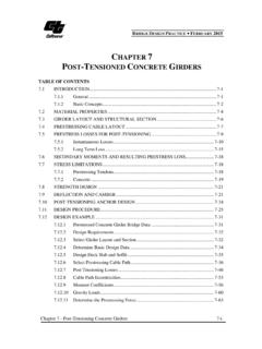
3 Example B-6 DEVIATION SADDLE design B-149 B-4 Example B-1 - COMPREHENSIVE Example problem DESCRIPTION The Example problem is a three span continuous box girder bridge that is 700 ft. long with span lengths of 200, 300 and 200 ft. It is assumed the bridge will be cast on falsework. Plan, elevation and section views are shown on the following pages. The centerline of the bridge lies on a 400 ft radius and the cross-section is a two cell box that is 43 -0 wide. This Example generally follows the AASHTO LRFD bridge design Specifications (4th Edition) and the recommended specification changes developed in this project.
4 Although the bridge parameters are near the limit of the type of bridge likely to be encountered in normal practice, the proposed specifications allow it to be analyzed for global response using a 3-dimensional spine beam. The first part of the Example uses this analysis method. The analysis in this Example was performed using the LARSA 4D Plus computer program. Most commercially available 3D structural analysis software is also suitable for this analysis. The Example follows the Analysis Guidelines included in Appendix C. The following Example illustrates how components critical to a curved bridge are designed for dead and live load, but is not a complete design of the entire bridge . The Example includes determination of longitudinal stress distribution; section design for shear, torsion and regional bending; and determination of bearing design forces.
5 The number of live load lanes applied to the bridge is based on the whole-width design approach described in AASHTO when primary bending and shear response of the individual girder lines is determined. A different number of lanes are applied when determining axial force, torsion and lateral bending and shear of the entire cross-section. In this case only the live load lanes that can fit on the bridge are considered. Our Research indicated that this approach yielded conservative results compared to placing individual live loads (lanes and trucks) eccentric to the centerline of the bridge and then combining these loads for maximum effect. This approach is also preferred to an individual girder line approach ( individual girder distribution factors) because it provides for a more direct combination of the multiple member actions encountered in a curved bridge of this type.
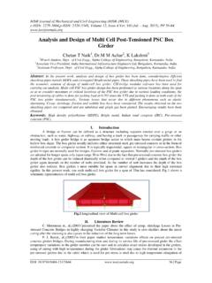
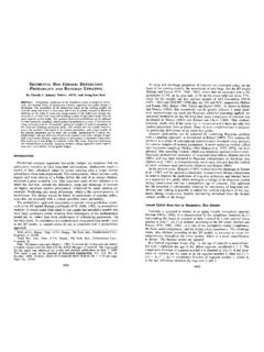
6 It also simplifies the application of live load. design for local tendon confinement is not included in this Example , but can be found in examples B-2 and B-3. B-5 Figure B-1 Plan and Elevation of Example problem bridge B-6801002030120 Abut 1 Bent 2 Symetric About9'-6"6'-0"1'-9"10'-4" Span 2P = 16,347 kips (Use 4 - 31 strand tendons per web)JACK Figure B-2 Prestress Path B-7 In addition to the 3-dimensional spine beam analysis, a grillage analogy analysis, also performed with LARSA 4D Plus, is presented. This analysis would not be required by the proposed specifications for this bridge , but is included to illustrate the analysis technique and for comparison of results. B-8 43'-0"5'-10"3'-0"25'-4"3'-0"5'-10"0'-8"1 '-0"0'-1018"0'-814"12'-0"1'-0"1'-0" Figure B-3 Typical Section - SECTION X-X 1'-9" Figure B-4 Section at Bent - SECTION Y-Y Figure B-5 - Column SectionB-9 Analysis Parameters Section Properties (From STAAD Section Wizaed): Figure B-6 -Typical Section Properties Overall dimensions ft x ft Ax Sectional area ft2Av,y Conventional shearing area along Y-axis ft2Av,z Conventional shearing area along Z-axis ft2Iy Moment of inertia about centroidal Y-axis 1,870 ft4Iz Moment of inertia about centroidal Z-axis 10,580 ft4Ix Torsional moment of inertia (St.)
7 Venant) 4166 ft4Sz Section modulus about Z-axis ft3 Syb Bottom section modulus about Y-axis Top section modulus about Y-axis ft3zM Distance from soffit to center of gravity along Z-axis ft B-10 Figure B-7 -Superstructure Section Properties at Bent Overall dimensions ft x 12 ft Ax Sectional area ,y Conventional shearing area along Y-axis ,z Conventional shearing area along Z-axis Moment of inertia about centroidal Y-axis 2,545ft4Iz Moment of inertia about centroidal Z-axis 11,790ft4Ix Torsional moment of inertia (St. Venant) 5,079ft4Sz Section modulus about Z-axis Top section modulus about Y-axis Bottom section modulus about Y-axis Distance to the center of gravity from soffit B-11ZY Figure B-8 -Pier Section Properties Overall dimensions ft x ft Ax Sectional area ft2 Av,z Conventional shearing area along Z-axis ft2 Av,y Conventional shearing area along Y-axis ft2 Iy Moment of inertia about centroidal Y-axis ft4 Iz Moment of inertia about centroidal Z-axis 2877ft4 Ix Torsional moment of inertia (St.
8 Venant) ft4 Sz Section modulus about Z-axis Sy Section modulus about Y-axis B-12 Loads: DC: Based on 150 pcf and member cross-section areas. Abutment Diaphragms = (ACP-AX) x WD x .150 = ( ) x x .150 = 160 kips DW: wDW = WDECK(wOVERLAY) + 2wRAIL = (.035) +2( ) = kips/ft PSFINAL: PJACK = NSTRAND*ASTRAND*fPS* = 31*3*4*(.217)(270)(.75) = 16,347 kips Anchor Set = inches = = .0002 Use Low Relaxation Strand fc 5000 psi Live Load Truck: Use HL93 with LARSA Live Load generator. Use one design truck per bridge and scale results by number of factored design lanes (NL) as determined on page B-37 Live Load Lane: Use kips/ft/lane. Use one lane and scale results by number of factored design lanes (NL) as determined on page B-37.
9 The maximum response from the following load cases and combinations was used. LLALLBLLCLLD = LLA + LLBLLE = LLB + LLCLLF = LLA + LLB + LLC Figure B-9 Elevation of bridge Showing Positions of Live Load Lane Loadings IM: Vehicle dynamic effect on design truck = B-13B-14 Global Spine Beam Analysis Input and Results LARSA Computer Output B-15B-16 LARSA Node Points B-17 LARSA Member NumbersB-18 Name Modulus of Elasticity (lb/in )Poisson Ratio Shear Modulus (lb/in )Unit Weight (lb/in )Thermal Expansion (1/ F *10^-6)Assigned X (ft)Origin Y (ft)Origin Z (ft)Axis Point X (ft)Axis Point Y (ft)Axis Point Z (ft)Point on XY Plane X (ft) Point on XY Plane Y (ft) Point on XY Plane Z (ft)Angle ZAngle XAngle Section Area (ft )Shear Area in yy (ft )Shear Area in zz (ft )Torsion Constant (ft^4)Inertia Izz (ft^4)Inertia Iyy (ft^4)Plastic Modulus Zyy (ft )Plastic Modulus Zzz (ft )Perimeter (ft)
10 Creep/Shrinkage Type Ductility Residual Strength (%) Assigned (NONE) (NONE) (NONE) (NONE)500 YesIDX (ft)Y (ft)Z (ft)Translation DOFR otation DOFD isplacement freeall freeall freeall freeall freeall freeall freeall freeall freeall freeall freeall freeall freeall freeall freeall freeall freeall freeall fixedall fixedall freeall freeall freeall freeall freeall freeall freeall freeall freeall freeall freeall freeall freeGlobalYesLARSA Input Data for Spine ModelINPUT : JointsINPUT : UCSsINPUT : Material PropertiesINPUT : freeall freeall freeall freeall freeall freeall , z fixedx , z fixedx fixedABUT4 YesIDI-JointJ-JointSpanTypeSection at StartSection at EndMaterialPrestress Force (kips)Length (ft)Rigid Zone from Start (x/L)Rigid Zone from End (x/L)Orientation Angle (deg)Casting (day)Structure / Construction Group71110104-BeamSuperstructure(same as start) (same as start) (same as start) (same as start) (same as start) (same as start) (same as start) (same as start) (same as start) (same as start) (same as start) (same as start) (same as start) (same as start) (same as start) (same as start) (same as start) (same as start) (same as start) (same as start) (same as start) (same as start) (same as start)