Transcription of Appendix F Fan Coil Unit Data - engr.psu.edu
1 Outreach Innovation Building Penn State Research Park State College, PA. Kyle Pepperman The Pennsylvania State University Mechanical Option Architectural Engineering Appendix F Fan Coil Unit Data Outreach Innovation Building Penn State Research Park State College, PA. Kyle Pepperman The Pennsylvania State University Mechanical Option Architectural Engineering Fan Coil Zone Schedule Fan Coil Zones Coil MBH Coil Ton Coil Type 1 1 2 3 4 3 5 6 12-2 2 7 12-4 3 8 12-2 4 9 10 24 12-2 5 11 23 12-4 6 12 13 14
2 25 12-2 7 15 16 29 12-2 8 17 18 12-2 9 19 20 21 12-2 10 22 12-2 11 1 25 2 12-2 12 3 2 11 12 13 12-2 13 9 53 53 12-2 14 10 12-2 15 14 15 12-2 16 16 12-4 *2 17 222b,j 12-2 18 19 727 120 12-6 *6 19 20 208 104 12-6 *2 20 24 25 27 351 117 12-6 *3 21 29 30 9 12-2 22 23 28 12-2 Outreach Innovation Building Penn State Research Park State College, PA.
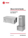
3 Kyle Pepperman The Pennsylvania State University Mechanical Option Architectural Engineering Coil Type Quantity12-2 16 12-4 4 12-6 11 Total 31 Air Terminal Devices400 to 3000 cfmBlower Coil Air HandlerBlower Coil Air Handler UNT-PRC003-ENSeptember 2002 ApplicationConsiderationsUNT-PRC003-EN8t he cooling and heating coils for flexibilityin flow rates, pressure drops, tempera-ture rise/drop, and fluid Cooling UnitsA BCHC/BCVC unit with a DX cooling coilwill often be connected to an air-cooledcondensing unit. Some condensing unitshave two, independent refrigerationcircuits, while the DX coil in the BCHC/BCVC unit is single-circuited.
4 Do notmanifold two, independent refrigerationcircuits into a single-circuited DX (evapo-rator) BCHC/BCVC has two methods forimproving the dehumidification perfor-mance of the constant-volume Fan Speed AdjustmentWhen equipped with a Tracer ZN520controller, the BCHC/BCVC unit can beoperated in the AUTO fan speed settingthat operates the fan at the lowest speedpossible, while maintaining spacetemperature setpoint. As the cooling loaddecreases, the first control step is toswitch the fan to operate at low a further drop in cooling load, thecontrol valve modulates to further reducethe unit s cooling capacity. This results inimproved dehumidification performancebecause less air passes through the coiland, therefore, leaves the coil at a cooler,drier provide the proper amount of outdoorair to the space at all fan speeds, theTracer ZN520 controller automaticallyadjusts the position of the economizerdamper when the fan switches adjustment has an addedacoustical advantage in that operating thefan at low speed results in Unit with ReheatBCHC/BCVC units equipped with a TracerZN520 controller and a hydronic heatingcoil in the reheat position will providedirect control of space humidity.
5 If thespace humidity level does not exceed thedesired upper limit, the unit responds toreduced cooling load by modulating thecontrol valve and, if in AUTO mode,switching between fan speeds. However,if the space humidity level rises above theupper limit, the capacity of the cooling coilis increased, overcooling the air tomaintain the space humidity below theApplication FlexibilityThe Trane blower coil air handler offers awide range of application flexibilitybetween the fan coil unit and the pack-aged climate are available in seven nominalcapacities ranging from to tonscooling and 400 to 3000 cfm airflow. Thebasic unit is available in horizontal (modelBCHC) as well as a vertical (model BCVC) single-zone, constant volumeapplications that we will discuss in thissection are: two-pipe hydronic two-pipe hydronic with electric heat four-pipe hydronic economizerOther applications of the BCHC/BCVC are: DX cooling two-pipe hydronic with steam heatingTwo-Pipe UnitsThe standard BCHC/BCVC unit isequipped with a hydronic coil.
6 The unitcan perform cooling only, heating andcooling (changeover system) or heatingonly. In a changeover system the unitcools during the spring, summer, and fallseasons (summer mode) and heatsduring the winter season (winter mode).Use the Trane Official Product SelectionSystem (TOPSS) program for specificdesign criteria such as flow rate, tem-perature rise/drop, pressure drop, glycolmixtures, and selecting two-pipe changeoverunits, note that TOPSS will only provideoutput that meets both the cooling andheating capacity requirements. Becausecooling and heating capacity require-ments for a given unit may differ signifi-cantly, a given coil may be optimally sizedfor one load and over/under sized for theother Units With Electric HeatWith the addition of electric heat, the two-pipe system can heat or cool.
7 In the non-changeover system the main coil isalways used for cooling and the electricheater is always used for heating. In thechangeover system, during the summermode (spring, summer and fall), the maincoil is used for cooling and electric heateris used for heating. During the wintermode, the main coil is used for heatingand the electric heater is systems with electric heat arean economical solution to the intermedi-ate season (spring and fall) comfortproblems associated with straight two-pipe systems. In moderate climates, orwhere electric rates are low, non-changeover systems are typically climates with significant heating loadsand/or high electric rates, a changeoversystem, to allow hydronic heating, istypically in Two-Pipe SystemsChanging between cooling and heatingmodes in a two-pipe system requiresenergy to heat or cool the mass of waterin the piping system at Standard 2001 definesspecific requirements for minimizing theenergy impact of this switchover: The system must allow a deadband,between changeover from one mode tothe other, of at least 15 F (8 C) outdoor-air temperature.
8 The system must include controls thatallow the system to operate in onemode for at least four hours beforechanging to the other mode. Reset controls must be provided toallow heating and cooling supply-watertemperatures, at the changeover point,to be no more than 30 F (17 C) UnitsThe addition of a one-row or two-rowheating coil to the basic BCHC/BCVC unitmakes it compatible for a four-pipecooling and heating system. The heatingcoil is available factory installed in eitherthe preheat or reheat systems solve the intermediateseason (spring and fall) comfort problemsassociated with straight two-pipe sys-tems because they only either cool orheat year-round. However, they dorequire chiller and boiler operation to beavailable to operate making the choice between a twoor four-pipe system, also consider: cooling/heating loads in perimeter zonesof the building the importance of temperature andhumidity control for the zone first costTOPSS allows independent selection ofApplicationConsiderationsUNT-PRC003-EN 9upper limit.
9 Then, the capacity of theheating coil modulates, adding a smallamount of heat to temper the air andavoid overcooling the Tracer ZN520 controller responds toa signal from a humidity sensor installedin the space or a signal from a buildingautomation system, and independentlymodulates the cooling and heating coils todirectly control both temperature andhumidity in the space. While this configu-ration can directly control indoor humiditylevels, it does require the boiler (or othersource of heat) to be available of Chilled-Water ResetIn many constant-flow pumping systems,the leaving chilled-water temperaturesetpoint is reset based on either outdoordry-bulb temperature or some indicationof cooling load.
10 Use caution whenimplementing a chilled-water resetstrategy because space humidity controlcan be compromised if the water gets BCHC/BCVC unit equipped with aTracer ZN520 can accept an input signalfrom a humidity sensor in the space. Abuilding automation system will continu-ally poll the humidity level in all spaces, orin a single representative space, to limitthe amount of chilled-water reset andmaintain space humidity EconomizerAdding a mixing box with a damperactuator allows economizer or freecooling applications. When using blowercoils for these applications, Trane highlyrecommends using a freeze protectiondevice to protect the coil(s). If the unit hasa Tracer ZN520 controller, you must havean outside air temperature signal fromeither a hardwired outside air sensor orfrom the building automation system,such as Tracer Summit.