Transcription of Fault Current Study - engr.psu.edu
1 DuBois Regional Medical Center West Wing Addition Benjamin Ardary - 91 2005 Lighting/Electrical Thesis Fault Current Study Introduction: A Fault Current analysis is probably one of the most crucial calculations of the electrical design process. This analysis allows designers to find the maximum available Fault Current at different points in the electrical system. The Fault Current found is then used to design and specify electrical components that can withstand the tremendous forces of faults without harming occupants and without damaging equipment. These faults are short circuit conditions in which the normal level of Current flow is suddenly increased by a factor of hundreds or even thousands, which is a deadly magnitude. For the purpose of this Study , a critical path was selected in the new addition that started at the utility pole and ended up at a distribution panel that serves branch circuits.
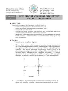
2 The crucial path that was selected ended up at the distribution panel WWNEC3L which is used to provide power to one of the C-section delivery rooms. Procedure: In order to perform a Fault Current analysis, you first have to obtain some information from the utility, manufacturers, and the designer. The information needed to perform this process is as follows: KVA Rating of Utility %Z & X/R Ratings of the Transformers Critical Path Wire Information (Length, Type, # Sets) The basic process of a Fault Current analysis is summing each component (transformers and conductors) together to get a total impedance at a particular point along the path. In order to sum these impedances, the individual resistances and reactances of all the components must first be summed. To start the calculations, the effective impedance of the utility on the secondary side of the main transformer must initially be determined.
3 Next, the impedance of the transformer must be added to the utility impedance to find the short circuit Current rating of the transformer. After finding the short circuit rating for the transformer you can move on down the line to the substation panelboard. To find the short circuit rating at this point, just add in the impendence of the feeder running from the transformer to the panel and calculate accordingly. The rest of the critical branch can be calculated this way (by adding impedances of the components to the previous total impedance). DuBois Regional Medical Center West Wing Addition Benjamin Ardary - 92 2005 Lighting/Electrical Thesis = = mRXZRUTILUTIL1tancos = =mKVAKVZUTILUTIL6210 = = mRXZXUTILUTIL1tansin = = mKVARXZKVR xfrmrxfrmr142tancos10% = = mKVARXZKVX xfrmrxfrmr142tansin10%AmpsZVItotalneutra llineSC= = 1000 = =msetsRLRconductor#1100 = =msetsXLRconductor#1100 NEC Code Requirements: Section Interrupting Rating.
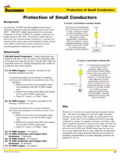
4 Fuses, Breakers and Disconnect Switches intended to interrupt Fault Current shall have an interrupting rating greater than the maximum available Fault Current available at the line side of the device. The Fault Current shall be determined at nominal system voltage. Section circuit Impedance and Other characteristics . The over- Current protective devices, the total impedance, the component short - circuit Current ratings, and circuit characteristics shall permit circuit clearing without extensive damage to the electrical components of the circuit . Equations Used: Utility Impedance: Transformer Impedances: Conductor Impedances: Fault Current Rating: DuBois Regional Medical Center West Wing Addition Benjamin Ardary - 93 2005 Lighting/Electrical Thesis Results: Conductor Impedances Segment # Sets Size Length (ft) R (m /100ft) X (m /100ft) Rcond.
5 (m ) Xcond. (m ) 1 1 500 KCMIL 15 2 1 500 KCMIL 15 3 11 500 KCMIL 20 4 9 500 KCMIL 200 5 3 500 KCMIL 25 6 3 500 KCMIL 10 7 3 250 KCMIL 5 8 4 350 KCMIL 5 9 1 4/o 120 Transformer Impedances xfrmr Primary V
6 Seconday V KVA %Z X/R Rxfrmr (m ) Xxfrmr (m ) A 34400 4100 3750 5 B 4100 480 2500 C 480 208 300 Summary of Results of Fault Analysis Point Location Available Fault Std. Bkr. Rating FA xfrmr A Secondary 9580 14000 FB Substation 9547 14000 FC xfrmr B Secondary 36924 50000 FD MDS-EPWW 36525 50000 FE MDP-WWGH 32965 35000 FF ATS-WW1G 34803 35000 FG DP-WWNECGH 35817 50000 FH xfrmr C Secondary 13675 14000 FI DP-WWNECGL 10520 14000 FJ WWNEC3LB 6475 10000