Transcription of Application Example 11/2016 Application examples for …
1 Application Example 11/2016 Application examples for High-Speed Counters (HSC) TIA Portal, S7-1200 warranty and Liability Application examples for High-Speed Counters (HSC) Entry ID: 109742346, , 11/2016 2 Siemens AG 2016 All rights reserved warranty and Liability Note The Application examples are not binding and do not claim to be complete with regard to configuration, equipment or any contingencies. The Application examples do not represent customer-specific solutions. They are only intended to provide support for typical applications . You are responsible for the correct operation of the described products. These Application examples do not relieve you of the responsibility of safely and professionally using, installing, operating and servicing equipment. When using these Application examples , you recognize that we cannot be made liable for any damage/claims beyond the liability clause described. We reserve the right to make changes to these Application examples at any time and without prior notice.
2 If there are any deviations between the recommendations provided in this Application Example and other Siemens publications e. g. catalogs the contents of the other documents shall have priority. We do not accept any liability for the information contained in this document. Any claims against us based on whatever legal reason resulting from the use of the examples , information, programs, engineering and performance data etc., described in this Application Example shall be excluded. Such an exclusion shall not apply in the case of mandatory liability, e. g. under the German Product Liability Act ( Produkthaftungsgesetz ), in case of intent, gross negligence, or injury of life, body or health, guarantee for the quality of a product, fraudulent concealment of a deficiency or breach of fundamental contractual obligations ( wesentliche Vertragspflichten ). The compensation for damages due to a breach of a fundamental contractual obligation is, however, limited to the foreseeable damage, typical for the type of contract, except in the event of intent or gross negligence or injury to life, body or health.
3 The above provisions do not imply a change of the burden of proof to your detriment. Any form of duplication or distribution of these Application examples or excerpts hereof is prohibited without the expressed consent of Siemens AG. Security informa-tion Siemens provides products and solutions with Industrial Security functions that support the secure operation of plants, systems, machines and networks. In order to secure plants, systems, machines and networks against cyber threats it is necessary to implement (and to maintain continuously) a holistic, state-of-the-art Industrial Security concept. With this in mind, Siemens products and solutions are only part of such a concept. It is the client s responsibility to prevent unauthorized access to his plants, systems, machines and networks. Systems, machines and components should only be connected with the company s network or the Internet, when and insofar as this is required and the appropriate protective measures (for Example , use of firewalls and network segmentation) have been taken.
4 In addition, the recommendations by Siemens regarding the respective protective measures have to be observed. For more information on Industrial Security, visit Siemens products and solutions undergo continuous development in order to make them even more secure. Siemens explicitly recommends to carry out updates as soon as the respective updates are available and always only to use the current product versions. Use of product versions that are no longer supported, and failure to apply latest updates may increase customer s exposure to cyber threats. In order to always be informed about product updates, subscribe to the Siemens Industrial Security RSS Feed at Table of Contents Application examples for High-Speed Counters (HSC) Entry ID: 109742346, , 11/2016 3 Siemens AG 2016 All rights reserved Table of Contents warranty and Liability .. 2 1 Introduction .. 4 4 Measuring the speed in case of only one pulse or a few pulses per rotation.
5 4 Determining the length by means of a HW gate .. 4 Determining the velocity by means of a HW gate .. 5 Components used .. 5 2 Engineering: Speed measurement .. 6 Hardware setup .. 6 Configuration .. 6 Integration into the user project .. 8 Period duration measurement using the "CTRL_HSC_EXT instruction .. 8 Calculating the speed .. 9 3 Engineering: Determining the length by means of a HW gate .. 10 Hardware setup .. 10 Configuration .. 10 Integration into the user project .. 13 4 Engineering: Determining the velocity by means of a HW gate .. 15 Hardware setup .. 15 Configuration .. 15 Integration into the user project .. 19 5 Appendix .. 23 Service and support .. 23 Links and literature .. 24 Change documentation .. 24 1 Introduction Application examples for High-Speed Counters (HSC) Entry ID: 109742346, , 11/2016 4 Siemens AG 2016 All rights reserved 1 Introduction In automation technology, there are many fast events that cannot be detected in the program cycle of the main OB.
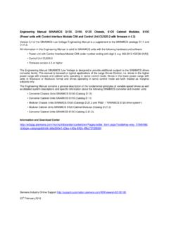
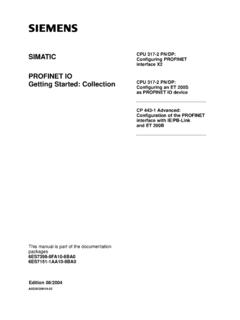
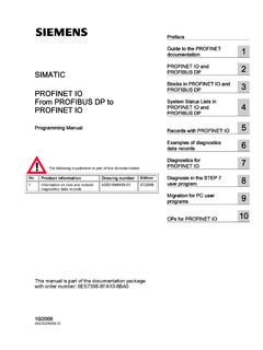
6 The high-speed counters (HSC) of the S7-1200 help you to process even those events. Overview This Application Example presents three possible applications for high-speed counters (HSC) of an S7-1200. Measuring the speed in case of only one pulse or a few pulses per rotation In the first Example , the instruction "CTRL_HSC_EXT" is used to determine the speed of a rotary motion in case of only one pulse or a few pulses per rotation. Figure 1-1: Speed measurement in case of one pulse per rotation HSC Determining the length by means of a HW gate The second Example explains the use of a HW gate. In this case, the pulses of an incremental encoder are counted as long as a light barrier detects an object. The number of pulses is used to calculate the size of an object given a known shifting length per pulse. Figure 1-2: Determining the length by means of a HW gate Others / inactiv ePulses of incremental encoderGate inputHSC 1 Introduction Application examples for High-Speed Counters (HSC) Entry ID: 109742346, , 11/2016 5 Siemens AG 2016 All rights reserved Determining the velocity by means of a HW gate In the third Example , the pulses of an incremental encoder (PWM) of the S7-1200 are counted by means of the HW gate as long as a light barrier detects an object.
7 The number of pulses and the cycle time of the PWM signal are used to determine the duration of the HIGH signal at the HW gate. The velocity will be calculated from the duration and the defined known size of an object. Figure 1-3: Determining the velocity by means of a HW gate Others / inactiv ePulses PWMGate inputHSC Note For precise time measurement, this Example uses the impulse encoder (PWM) with a time base of 10 s. Components used This Application Example has been created with the following hardware and software components: Table 1-1 Component Qty. Article number Note CPU 1214C DC/DC/DC 1 6ES7214-1AG40-0XB0 Alternatively, any other CPU of the S7-1200 with firmware can also be used. STEP 7 Professional V14 1 - This Application Example consists of the following components: Table 1-2 Component File name Note Documentation - STEP 7 project - 2 Engineering: Speed measurement Application examples for High-Speed Counters (HSC) Entry ID: 109742346, , 11/2016 6 Siemens AG 2016 All rights reserved 2 Engineering: Speed measurement The Example for measuring the speed in case of only one pulse or a few pulses per rotation has been realized in the STEP 7 project Ex01_Speed.
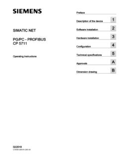
8 Hardware setup Figure 2-1: Hardware setup for speed measurement CPU 1214C DC/DC/DCDQ +M1ML+ +3M Note Use a precise and highly responsive sensor. Use shielded cables for high-frequency signals. Configuration Configuring a high-speed counter To configure a high-speed counter, proceed as follows: 1. In the device or network view, select an S7-1200 CPU. 2. In the inspector window, go to Properties > General > High speed counters (HSC) and click the high-speed counter "HSC1". 3. Enable the high-speed counter in the General parameter group by ticking the corresponding checkbox. Under Project information , you can enter a name and a comment for the counter. Figure 2-2: Enabling the HSC 2 Engineering: Speed measurement Application examples for High-Speed Counters (HSC) Entry ID: 109742346, , 11/2016 7 Siemens AG 2016 All rights reserved 4. In the Function parameter group, define the functioning of the counter as follows: "Type of counting": Period Operating phase : Single phase "Counting direction is specified by": "User program (internal direction control)" "Initial counting direction": "Count up" "Frequency measuring period": sec Figure 2-3: Function of the HSC 5.
9 In the Hardware inputs parameter group, go to "Clock generator input" and enter the hardware input "% ". Figure 2-4: Hardware input for clock generator 6. In the "I/O addresses area, you can set the parameters of the input addresses. Configuring a digital input To ensure safe detection of the clock generator pulses, the filter time of the digital input must be set to be less than the duration of the input signal. Set the filter time as follows: 1. In the device or network view, select an S7-1200 CPU. 2. In the inspector window, go to "Properties > General > DI 14/DQ 10 > Digital inputs and click "Channel0". 3. Set the "Input filters", e. g. millisec". Figure 2-5: Input filters for clock generator 2 Engineering: Speed measurement Application examples for High-Speed Counters (HSC) Entry ID: 109742346, , 11/2016 8 Siemens AG 2016 All rights reserved Integration into the user project Period duration measurement using the "CTRL_HSC_EXT instruction Calling the CTRL_HSC_EXT instruction Using the instruction "CTRL_HSC_EXT" ( Control high-speed counters (extended) ), you can configure and control the high-speed counters supported by the CPU.
10 The "CTRL_HSC_EXT" instruction supports period duration measurement. It offers program access to the number of input pulses over a specified measurement interval. The instruction is called in the cyclic program as follows. Figure 2-6: Calling the CTRL_HSC_EXT instruction At the "HSC" input, specify the hardware identifier (HW-ID) of the high-speed counter "HSC1". The "CTRL" parameter requires a tag of system data type "HSC_Period". Using the system data type "HSC_Period" The tag of system data type "HSC_Period" is defined in the data block "DataExample1". Figure 2-7: Structure of the system data type "HSC_Period" "ElapsedTime" specifies the time in nanoseconds between the last counting events of successive measurement intervals. "EdgeCount" outputs the number of counting events received during a measurement interval. With the start value "TRUE" for "EnHSC", the measurement is permanently enabled. For the "NewPeriod" parameter, specify the interval of the period measurement in milliseconds.