Transcription of Application Note 17 - Microchip Technology
1 October 19981 Application Note 17 Application Note 17 MicrelApplication Note 17 universal serial Bus Power Managementby Kevin LynnIntroductionPower management and distribution is a major factor incorrectly designing USB ( universal serial Bus) methods of designing USB peripheral power distribu-tion are crucial to ensure full compliance with the USBspecification, including compliance with electromagnetic in-terference (EMI) and voltage regulation ClassesUSB defines several device classes, differentiated by theirpower requirements or capabilities. The most important de-vice classes are hubs and provide for distribution of data and power to down-stream (away from the host) devices and communicate withthe host.
2 Hubs may be either locally powered (self-powered),bus-powered from an upstream cable (toward the host), or acombination of the hubs have a local power supply. Examplesare PCs (host), stand-alone hubs, monitors, printers, scan-ners, or docking stations, which may draw up to 100mA (oneunit load) from an upstream port. Self-powered hubs arerequired to limit and report overcurrent conditions and maysupply up to 500mA to each downstream hubs obtain all power from the bus (a cable toan upstream self-powered hub) and may supply 100mA ormore to each downstream port if the input power budget is notexceeded. Bus-powered hubs may draw 100mA at start-upfrom an upstream hub, increasing up to 500mA after enu-meration, apportioning the power in increments of 100mA perdownstream port plus 100mA internally.
3 Bus-powered hubsmust provide power switching for downstream ports on a perport basis or have a single switch for all of the ports (gang-mode power control).Micrel, Inc. 1849 Fortune Drive San Jose, CA 95131 USA tel + 1 (408) 944-0800 fax + 1 (408) 944-0970 are endpoint low- or high-power devices and do notrepeat data or provide downstream functions may initially draw 100mA at an upstream self-powered port, increasing after enu-meration up to 500mA. If, during enumeration, there isinsufficient power available from upstream, the remainder ofthe function is not powered and a power limit warning mes-sage is sent. Self-powered functions may draw 100mA fromupstream with the remainder from a local power functions may draw up to 100mA from anupstream Power DistributionConnection between devices are made using cables whichare either detachable (such as a USB modem) or perma-nently attached (such as a keyboard).
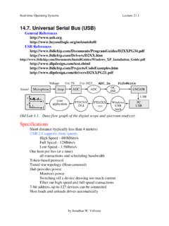
4 High speed (> ) peripherals require shielded cable, while low-speed pe-ripherals may operate with unshielded cable to minimizecost. The upstream port of a hub is, by definition, a high-speed port and requires a shielded cable. Figure 1 shows thevoltage regulation requirements of a USB system based oncurrent USB Hub RequirementsUSB self-powered hubs are required to provide a minimum at downstream ports under all legal load hubs may draw up to 100mA operating currentfrom an upstream comply with UL defined safety requirements, current fromany port must be limited to less than 25VA (5A for 5V ports).If such an overcurrent condition occurs, even if it is onlymomentary, it must be reported to the hub controller.
5 Detec-tion of overcurrent must disable all affected ports. If 500mA to Self-Powered HubFigure 1. Typical USB Voltage Distribution SystemApplication Note 17 MicrelApplication Note 172 October 1998overcurrent condition has caused a permanent disconnect(such as a blown fuse), the hub must report it upon completingits reset or protection may be implemented on all down-stream ports in aggregate (ganged), or on an individual (perport) basis. Overcurrent limiting devices may include polyfuses,standard fuses, or a solid-state switch. A practical limit isseven downstream ports per protection Regulation RequirementsThe dc output voltage, measured at the board side of the self-powered hub downstream connector, must remain and above under all legal continuous internal power supply tolerance dictates the allowablecomponent voltage drops within a self-powered hub.
6 Table 1depicts the range of resistance of the overcurrent protectiondevice, assuming a 30mV (or 60m ) drop across the PCBcomponents. For example, Table 1 shows that using a 5V,3% power supply allows a maximum resistance of 140m forthe overcurrent protection device. A , 3% supply allowsfor a 340m device. If it is expected that the PCB componentvoltage drops will be other than 30mV, then these values canbe scaled components that make up the voltage drop include thecircuit trace, overcurrent protection device, and output filterferrite beads. The printed circuit board power and groundtraces, solder connections, and ferrite beads on both powerand ground output lines may total 60m , dropping a total of30mV at Additional traces, ferrite beads, and protectiondevices are needed for each output port.
7 Figure 2 representsthe component voltage drops of a typical self-powered Droop RequirementsUSB supports dynamic attachment (hot plug-in) of peripher-als. A current surge is caused by the input capacitance of thedownstream device. Ferrite beads are recommended inseries with all power and ground connector pins. Ferritebeads reduce EMI and limit the inrush current during hot-attachment by attenuating high-frequency signals while dccurrent passes freely. The simplest ferrite beads consist of asmall ferrite tube on a tinned solid copper wire. The resis-tance of the ferrite bead wire should be as low as possible,with a large solder-pad to minimize connection requires that momentary droop of the at a bus-powered hub s upstream cable connector never goes Power to 5mV5mV(trace resistance) 500mA 33 F* Ferrite Bead(solder joint resistance) FUSB Self-Powered Hub1/2 MIC2526 Switch(+)( )CableConnectorDownstreamPeripheral max.
8 * Tantalum or 100 F electrolytic, per portFigure 2. Self-Powered Hub Per-Port Voltage % % % % % % % % % % % % % % % % % % % % % % % % % % % % Table 1. Maximum Allowed On-Resistancewith 30mV PCB Voltage Drop** Shading represents USB-compliant 19983 Application Note 17 Application Note 17 MicrelBulk capacitance of at least 120 F per hub is required. Thisbulk capacitance provides the short-term transient currentneeded during a hot-attachment event. A four-port hub witha 33 F, 16V tantalum capacitor mounted close to eachdownstream connector (see Figures 5, 6, 7, and 8) shouldhave hot-plug droop much less than 330mV. If electrolyticcapacitors are substituted, 100 F, 10V units should providesimilar transient droop protection.
9 Figure 3 shows the waveforms for a typical hot-plug eventusing the circuit of Figure 6. The hub output capacitorsupplies the bulk of the inrush current to the downstream unitload (44 , 10 F). This current exceeds 2A for less than 10 adjacent port voltage droop of 142mV is well within the330mV specification steady loadTIME (10 s/div.)IOUT(Port 1)500 (Port 2) peakFigure 3. Typical Hot-Plug EventDetach Transient SurgeWhen current in a wire is interrupted, the inductance of thewire may cause a voltage spike as the magnetic field col-lapses. To reduce these spikes, which generate EMI, and toprevent damage to components, F, 25V ceramic by-pass capacitors should be installed directly from VBUS pin tothe ground pin at each Circuit LayoutThe power circuitry of USB printed circuit boards requires acustomized layout to maximize thermal dissipation and tominimize voltage drop and circuit power and ground traces should be wider thantraces used in a normal digital layout to reduce their in-circuitresistance.
10 Each solder or header connection may be ex-pected to contribute up to 10m , emphasizing the impor-tance of trace resistance reduction. Table 2 shows typicalresistance in m /inch for standard conductor widths via connections may each have 15m resis-tance. If a power trace traverses through a board, usemultiple vias to reduce the interconnect resistance. Placingtraces on both sides of the board, connected with multiplevias, can cut the trace resistance in half. Solder plating on thesolder-side also reduces trace and wide same-side traces generally reduce voltagedrop. Ground planes should have a separation line betweenoutput ports to isolate transient droop during planes are good thermal radiators and provide (inches)(m /inch)1 2 2.