Transcription of ATtiny13A Data Sheet - Microchip Technology
1 2021 Microchip Technology Inc. data Sheet CompleteDS40002307A-page 1 Features High Performance, Low Power AVR 8-Bit Microcontroller Advanced RISC Architecture 120 Powerful Instructions Most Single Clock Cycle Execution 32 x 8 General Purpose Working Registers Fully Static Operation Up to 20 MIPS Througput at 20 MHz High Endurance Non-volatile Memory segments 1K Bytes of In-System Self-programmable Flash program memory 64 Bytes EEPROM 64 Bytes Internal SRAM Write/Erase Cycles: 10,000 Flash/100,000 EEPROM data retention: 20 Years at 85 C/100 Years at 25 C (see page 12) Programming Lock for Self-Programming Flash & EEPROM data Security Peripheral Features One 8-bit Timer/Counter with Prescaler and Two PWM Channels 4-channel, 10-bit ADC with Internal Voltage Reference Programmable Watchdog Timer with Separate On-chip Oscillator On-chip Analog Comparator Special Microcontroller Features debugWIRE On-chip Debug System In-System Programmable via SPI Port External and Internal Interrupt Sources Low Power Idle, ADC Noise Reduction, and Power-down Modes Enhanced Power-on Reset Circuit Programmable Brown-out Detection Circuit with Software Disable FunctionATtiny13 AtinyAVR data SheetIntroductionThe ATtiny13A is a low-power CMOS 8-bit microcontroller based on the AVR enhanced RISC architec-ture.
2 By executing powerful instructions in a single clock cycle, the ATtiny13A achieves throughputsapproaching 1 MIPS per MHz allowing the system designer to optimize power consumption versus pro-cessing speed. 2021 Microchip Technology Inc. data Sheet CompleteDS40002307A-page 2 ATtiny13A Internal Calibrated Oscillator I/O and Packages 8-pin PDIP/SOIC/SOIJ: Six Programmable I/O Lines 10-pad VDFN: Six Programmable I/O Lines 20-pad WQFN: Six Programmable I/O Lines Operating Voltage: Speed Grade: 0 4 MHz @ 0 10 MHz @ 0 20 MHz @ Industrial Temperature Range Low Power Consumption Active Mode: 190 A at V and 1 MHz Idle Mode: 24 A at V and 1 MHzATtiny13A 2021 Microchip Technology Inc.
3 data Sheet Complete DS40002307A-page 3 Table of Contents1 Pin Configurations .. Description .. 22 Overview .. Diagram .. 33 About .. Examples .. 54 CPU Core .. Arithmetic Logic Register .. Purpose Register File .. Pointer .. Execution Timing .. and Interrupt 115 Memories .. Reprogrammable Flash Program Memory .. data data Memory .. Memory .. Description .. 196 System Clock and Clock Options .. Systems and their Distribution .. Sources .. Clock Prescaler .. Description .. 267 Power Management and Sleep Modes .. BOD Reduction Register .. Power Consumption .. 31 ATtiny13A 2021 Microchip Technology Inc.
4 data Sheet Complete DS40002307A-page 4 Description .. 328 System Control and Reset .. the AVR .. Sources .. Voltage Reference .. Timer .. Description .. 419 Interrupts .. Vectors .. Interrupts .. Description .. 4610 I/O Ports .. as General Digital I/O .. Port Functions .. Description .. 5611 8-bit Timer/Counter0 with PWM .. Clock Sources .. Unit .. Compare Match Output Unit .. of Operation .. Timing Diagrams .. Description .. 6912 Timer/Counter Prescaler .. Reset .. Clock Source .. Description.. 7713 Analog Comparator .. Comparator Multiplexed Input .. Description .. 79 ATtiny13A 2021 Microchip Technology Inc.
5 data Sheet Complete DS40002307A-page 5 14 Analog to Digital Converter .. a Conversion .. and Conversion Timing .. Channel or Reference Selection .. Noise Canceler .. Input Circuitry .. Noise Canceling ADC Accuracy Definitions .. ADC Conversion Register Description .. 9115 debugWIRE On-chip Debug System .. Interface .. Break Points .. of debugWIRE .. Description .. 9616 Self-Programming the Flash .. Page Erase by the Temporary Buffer (Page Loading).. a Page Write .. the Flash During Self-Programming .. Write Prevents Writing to SPMCSR .. Fuse and Lock Bits from Firmware .. Flash Corruption .. Time for Flash when Using SPM.
6 Description .. 10117 Memory Programming .. And data Memory Lock Bits .. Bytes .. Bytes .. 104 ATtiny13A 2021 Microchip Technology Inc. data Sheet Complete DS40002307A-page 6 Size .. Programming .. Serial Programming .. for Efficient Programming .. 11218 Electrical Characteristics .. Maximum Ratings* .. Characteristics .. and Reset Characteristics .. Comparator Characteristics .. Programming Characteristics .. Serial Programming Characteristics .. 12219 Typical Characteristics .. Current of I/O Modules .. Consumption in Active Mode .. Consumption in Idle Mode .. Consumption in Power-down Consumption in Reset.
7 Consumption of Peripheral Units .. Resistors .. Driver Strength (Low Power Pins) .. Driver Strength (Regular Pins).. Input Thresholds and Hysteresis (for I/O Ports) .. BOD, Bandgap and Reset .. Internal Oscillator Speed .. 15320 Register Summary .. 15721 Instruction Set Summary .. 15922 Ordering Information .. 16123 Packaging Information .. 164 ATtiny13A 2021 Microchip Technology Inc. data Sheet Complete DS40002307A-page 7 16624 Errata .. Rev. G H .. Rev. E F .. Rev. A D .. 16725 Datasheet Revision History .. 8126F 05/12 .. 8126E 07/10 .. 8126D 11 8126C 09 8126B 11/08 .. 8126A 05/08.
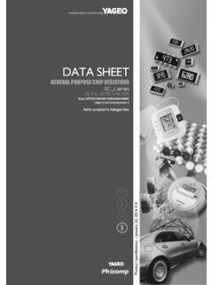
8 168 ATtiny13A 2021 Microchip Technology Inc. data Sheet Complete DS40002307A-page 8 1. Pin ConfigurationsFigure of ATtiny13A12348765(PCINT5/RESET/ADC0/dW) PB5(PCINT3/CLKI/ADC3) PB3(PCINT4/ADC2) PB4 GNDVCCPB2 (SCK/ADC1/T0/PCINT2)PB1 (MISO/AIN1/OC0B/INT0/PCINT1)PB0 (MOSI/AIN0/OC0A/PCINT0)8-PDIP/SOIJ/SOIC1 234520-WQFN15141312112019181716678910(PC INT5/RESET/ADC0/dW) PB5(PCINT3/CLKI/ADC3) PB3 DNCDNC(PCINT4/ADC2) PB4 DNCDNCGNDDNCDNCVCCPB2 (SCK/ADC1/T0/PCINT2)DNCPB1 (MISO/AIN1/OC0B/INT0/PCINT1)PB0 (MOSI/AIN0/OC0A/PCINT0)DNCDNCDNCDNCDNCNO TE: Bottom pad should be soldered to : Do Not Connect1234510-VDFN10 9 8 7 6(PCINT5/RESET/ADC0/dW) PB5(PCINT3/CLKI/ADC3) PB3 DNC(PCINT4/ADC2) PB4 GNDVCCPB2 (SCK/ADC1/T0/PCINT2)DNCPB1 (MISO/AIN1/OC0B/INT0/PCINT1)PB0 (MOSI/AIN0/OC0A/PCINT0)NOTE: Bottom pad should be soldered to.
9 Do Not ConnectATtiny13A 2021 Microchip Technology Inc. data Sheet Complete DS40002307A-page 9 B (PB5:PB0)Port B is a 6-bit bi-directional I/O port with internal pull-up resistors (selected for each bit). ThePort B output buffers have symmetrical drive characteristics with both high sink and sourcecapability. As inputs, Port B pins that are externally pulled low will source current if the pull-upresistors are activated. The Port B pins are tri-stated when a reset condition becomes active,even if the clock is not B also serves the functions of various special features of the ATtiny13A as listed on input. A low level on this pin for longer than the minimum pulse length will generate areset, even if the clock is not running and provided the reset pin has not been disabled.
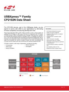
10 The min-imum pulse length is given in Table 18-4 on page 126. Shorter pulses are not ensured togenerate a reset pin can also be used as a (weak) I/O 2021 Microchip Technology Inc. data Sheet Complete DS40002307A-page 10 2. OverviewThe ATtiny13A is a low-power CMOS 8-bit microcontroller based on the AVR enhanced RISC architecture. By executing powerful instructions in a single clock cycle, the ATtiny13A achievesthroughputs approaching 1 MIPS per MHz allowing the system designer to optimize power con-sumption versus processing DiagramFigure DiagramPROGRAMCOUNTERINTERNALOSCILLATORW ATCHDOGTIMERSTACKPOINTERPROGRAMFLASHSRAM MCU CONTROLREGISTERGENERALPURPOSEREGISTERSIN STRUCTIONREGISTERTIMER/COUNTER0 INSTRUCTIONDECODERDATA BDATA REGISTERPORT BPROGRAMMINGLOGICTIMING ANDCONTROLMCU STATUSREGISTERSTATUSREGISTERALUPORT B DRIVERSPB[0:5]VCCGNDCONTROLLINES8-BIT DATABUSZ ADC / ANALOG COMPARATORINTERRUPTUNITCALIBRATEDYXRESET CLKIWATCHDOGOSCILLATORDATAEEPROMAT tiny13A 2021 Microchip Technology Inc.