Transcription of Attitude Determination and Control (ADCS)
1 Attitude Determination and Control (ADCS). Space Systems Product Development Spring 2001. Olivier L. de Weck Department of Aeronautics and Astronautics Massachusetts Institute of Technology ADCS Motivation Motivation Sensors: GPS, star trackers, limb In order to point and slew optical sensors, rate gyros, inertial systems, spacecraft Attitude Control measurement units provides coarse pointing while Control Laws optics Control provides fine Spacecraft Slew Maneuvers pointing Euler Angles Spacecraft Control Quaternions Spacecraft Stabilization Spin Stabilization Key Question: Gravity Gradient What are the pointing Three-Axis Control requirements for satellite ? Formation Flight NEED expendable propellant: Actuators Reaction Wheel Assemblies On-board fuel often determines life (RWAs) Failing gyros are critical ( HST). Control Moment Gyros (CMGs). Magnetic Torque Rods Thrusters Outline Definitions and Terminology Coordinate Systems and Mathematical Attitude Representations Rigid Body Dynamics Disturbance Torques in Space Passive Attitude Control Schemes Actuators Sensors Active Attitude Control Concepts ADCS Performance and Stability Measures estimation and Filtering in Attitude Determination Maneuvers Other System Consideration, Control /Structure interaction Technological Trends and Advanced Concepts Opening Remarks Nearly all ADCS Design and Performance can be viewed in terms of RIGID BODY dynamics Typically a Major spacecraft system For large, light-weight structures with low fundamental frequencies the flexibility needs to be taken into account ADCS requirements often drive overall S/C design Components are cumbersome, massive and power-consuming Field-of-View requirements and specific orientation are key Design.
2 Analysis and testing are typically the most challenging of all subsystems with the exception of payload design Need a true systems orientation to be successful at designing and implementing an ADCS. Terminology Attitude : orientation of a defined spacecraft body coordinate system with respect to a defined external frame (GCI,HCI). Attitude Determination : Real-Time or Post-Facto knowledge, within a given tolerance, of the spacecraft Attitude Attitude Control : Maintenance of a desired, specified Attitude within a given tolerance Attitude ERROR: Low Frequency spacecraft misalignment;. usually the intended topic of Attitude Control Attitude JITTER: High Frequency spacecraft misalignment;. usually ignored by ADCS; reduced by good design or fine pointing/optical Control . Pointing Control Definitions target target desired pointing direction estimate true actual pointing direction (mean). estimate estimate of true (instantaneous). a pointing accuracy (long-term).
3 C a s stability (peak-peak motion). k true k knowledge error c Control error s a = pointing accuracy = Attitude error s = stability = Attitude jitter Source: G. Mosier NASA GSFC. Attitude Coordinate Systems (North Celestial Pole). ^. GCI: Geocentric Inertial Coordinates Z. Cross product ^ ^ ^ Geometry: Celestial Sphere Y=ZxX. n gth le dihedral Arc G. D. ^. Y. VERNAL ^. X. EQUINOX. D : Right Ascension Inertial Coordinate G : Declination System X and Y are in the plane of the ecliptic Attitude Description Notations { } = Coordinate system Z A *. P = Vector A* A*. Pz P P = Position vector { A}. Py Y A Px . Px A* . P = Py . X A P . z . 1 0 0 . [ ]. Unit vectors of { A} = X A Y A Z A = 0 1 0 .. 0 0 1 . Describe the orientation of a body: (1) Attach a coordinate system to the body (2) Describe a coordinate system relative to an inertial reference frame Rotation Matrix Z A { A} = Reference coordinate system Jefferson Z B Memorial Y . B { B} = Body coordinate system Rotation matrix from {B} to {A}.
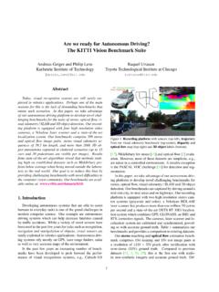
4 Y A. X A. X B. A. B R =[A . X A A . B YB ZB ]. Z A Special properties of rotation matrices: Jefferson Z MemorialY . B B (1) Orthogonal: RT R = I , RT = R 1.. Y A (2) Orthonormal: X A X B R =1. 1 0 0 . (3) Not commutative A. B R = 0 cos - sin . A B B A. 0 sin cos B R C R C R BR. Euler Angles (1). Euler angles describe a sequence of three rotations about different axes in order to align one coord. system with a second coord. system. Rotate about Z A by Rotate about Y B by Rotate about X C by . Z A Z B Z B Z C. Z C Z D. Y B Y D. Y B .. Y A X B. X A. Y C Y C. X B X C X C X D. cos - sin 0 cos 0 sin 1 0 0 . 0 0 . B R = sin cos D R = 0 cos - sin . A B C. CR= 0 1.. 0 0 1 - sin 0 cos 0 sin cos . A A B C. D R= B R C R D R. Euler Angles (2). Concept used in rotational about Yi Zi (parallel to r). kinematics to describe body about X'. orientation inertial frame about Zb Yaw Sequence of three angles and Roll Body prescription for rotating one Xi (parallel CM.)
5 Reference frame into another to v). Can be defined as a transformation Pitch matrix body/inertial as shown: TB/I (r x v direction). Yi Euler angles are non-unique and r exact sequence is critical nadir Goal: Describe kinematics of body-fixed TB /1I = TI / B = TBT/ I. Note: frame with respect to rotating local vertical (Pitch, Roll, Yaw) = (T I \) Euler Angles Transformation cos sin 0 1 0 0 cos 0 -sin . from Body to T = -sin cos 0 0 cos sin 0 1 0 . Inertial frame: B/I . 0 0 1 0 -sin cos sin 0 cos . YAW ROLL PITCH. Quaternions *. q = A vector describes the Main problem computationally is q1 . the existence of a singularity q q* axis of rotation.. Q = = q4 = A scalar describes the 2. Problem can be avoided by an q3 q4 . application of Euler's theorem: amount of rotation. 4 . q A . Z A K. EULER'S THEOREM. Jefferson Memorial Z B Y B. The orientation of a body is uniquely specified by a vector giving the direction of a body axis and a scalar specifying a Y A.
6 Rotation angle about the axis. X A. X B. Definition introduces a redundant . A: Inertial q1 = k x sin . fourth element, which eliminates B: Body 2 . the singularity.. q2 = k y sin . This is the quaternion concept k x 2 . Quaternions have no intuitively A . K = k y q3 = k z sin . interpretable meaning to the human k 2 . mind, but are computationally z .. convenient q4 = cos . 2 . Quaternion Demo (MATLAB). Comparison of Attitude Descriptions Method Euler Direction Angular Quaternions Angles Cosines Velocity Z. Pluses If given , , orientation Vector Computationally then a unique defines a properties, robust orientation is unique dir-cos commutes Ideal for digital defined matrix R addition Control implement Minuses Given orient 6 constraints Integration Not Intuitive then Euler must be met, time does not Need transforms non-unique non-intuitive give orientation Singularity Needs transform Must store Best for Best for initial condition digital Control analytical and implementation ACS design work Rigid Body Kinematics Z Body Time Derivatives: CM.
7 (non-inertial). U. r ^ ^j k ^ Rotating K. Z = Angular velocity ^i Body Frame Inertial R. of Body Frame Frame Y. J^. ^. X I. Applied to BASIC RULE: INERTIAL = BODY + . position vector r: r = R+ Position Expressed in r = R + BODY + Rate the Inertial Frame r=R. + . BODY. + 2 .. BODY. + . + ( ) Acceleration Inertial relative accel angular coriolis centripetal accel of CM CM accel Angular Momentum (I).. rn mn Angular Momentum Z . ri n rn mi r i mi r i System in H total = motion relative ri i =1 to Inertial Frame m1. r1 . r1. Y. If we assume that X Collection of point (a) Origin of Rotating Frame in Body CM masses mi at ri (b) Fixed Position Vectors ri in Body Frame (Rigid Body). Angular Momentum Decomposition Then : Note that Ui is n n . mi R R mi i i measured in the H total = + inertial frame i =1 i =1. ANGULAR MOMENTUM H BODY. OF TOTAL MASS BODY ANGULAR. INERTIAL ORIGIN MOMENTUM ABOUT. CENTER OFMASS. Angular Momentum (II). For a RIGID BODY i = i ,BODY + i = i we can write: RELATIVE.
8 MOTION IN BODY. And we are able to write: H = I RIIGID BODY, CM COORDINATES. H and Z are resolved in BODY FRAME. The vector of angular momentum in the body frame is the product of the 3x3 Inertia matrix and the 3x1 vector of angular velocities.. Inertia Matrix Real Symmetric ; 3x3 Tensor ; coordinate dependent Properties: ( ). n n I11 = mi i22 + i23 I12 = I 21 = mi i 2 i1. i =1 i =1. I11 I12 I13 . ( ). n n I = I 21 I 22 I 23 I 22 = mi i21 + i23 I13 = I 31 = mi i1 i 3. i =1 i =1. I 31 I 32 I 33 . ( ). n n I 33 = mi i21 + i22 I 23 = I 32 = mi i 2 i 3. i =1 i =1. Kinetic Energy and Euler Equations 1 n 2 1 n Kinetic Etotal = mi R + mi i2. Energy 2 i =1 2 i =1. E-TRANS E-ROT. For a RIGID BODY, CM Coordinates 1 1. with Z resolved in body axis frame EROT = H = T I . 2 2. H = T I Sum of external and internal torques In a BODY-FIXED, PRINCIPAL AXES CM FRAME: Euler Equations H 1 = I1 1 = T1 + ( I 22 I 33 ) 2 3 No general solution exists. H 2 = I 2 2 = T2 + ( I 33 I11 ) 3 1.
9 Particular solutions exist for simple torques. Computer simulation usually required. H = I = T + ( I I ) . 3 3 3 3 11 22 1 2. Torque Free Solutions of Euler's Eq. TORQUE-FREE An important special case is the torque-free motion of a (nearly). CASE: symmetric body spinning primarily about its symmetry axis By these assumptions: x , y << z = I xx I yy The components of angular velocity And the Euler equations become: then become: x (t ) = xo cos n t I zz I yy y (t ) = yo cos n t x = y I xx The Zn is defined as the natural . or nutation frequency of the body: n2 = K x K y 2 Kx I zz I xx Z Z Z Q H y = y H I yy Z. Ky Q Space z = 0. e Bo Bod on Cone dy eC. y Co H and Z never align ac Con Sp ne Q : nutation unless spun about Iz > Ix = I y e Iz < Ix = I y angle a principal axis ! Spin Stabilized Spacecraft UTILIZED TO STABILIZE SPINNERS. Zb Perfect Cylinder : m L 2 . 2. Antenna I xx = I yy = + R . despun at 4 3 . 1 RPO. mR 2. I zz =. 2 Yb Xb DUAL SPIN.
10 Two bodies rotating at different rates about a common axis Behaves like simple spinner, but part is despun (antennas, sensors). : requires torquers (jets, magnets) for BODY momentum Control and nutation dampers for stability allows relaxation of major axis rule Disturbance Torques Assessment of expected disturbance torques is an essential part of rigorous spacecraft Attitude Control design Typical Disturbances Gravity Gradient: Tidal Force due to 1/r2 gravitational field variation for long, extended bodies ( Space Shuttle, Tethered vehicles). Aerodynamic Drag: Weathervane Effect due to an offset between the CM and the drag center of Pressure (CP). Only a factor in LEO. Magnetic Torques: Induced by residual magnetic moment. Model the spacecraft as a magnetic dipole. Only within magnetosphere. Solar Radiation: Torques induced by CM and solar CP offset. Can compensate with differential reflectivity or reaction wheels. Mass Expulsion: Torques induced by leaks or jettisoned objects Internal: On-board Equipment (machinery, wheels, cryocoolers, pumps etc ).