Transcription of Tilt Sensing Using Linear Accelerometers
1 Freescale SemiconductorDocument Number: AN3461 Application NoteRev. 6, 03/2013 2007-2009, 2012-2013 Freescale Semiconductor, Inc. All rights Sensing Using a Three-Axis Accelerometerby: Mark Pedley1 IntroductionAccelerometers are sensitive to both Linear acceleration and the local gravitational field. The former provides information on taps and other handset motions allowing the development of 'gesture' user interfaces while the latter provides information on the accelerometer orientation which allows a smartphone or tablet display to automatically switch between portrait and landscape application note documents the mathematics of orientation determination Using a three-axis accelerometer. The techniques are applicable to both digital Accelerometers and, after signal digitization, to analog Accelerometers . For convenience, it is assumed that the accelerometer is mounted in a smartphone or tablet but the arguments apply to any product with an embedded three-axis.
2 Key Words .. Summary .. 22 Accelerometer Output Under Gravity and Acceleration.. 33 Pitch and Roll estimation .. 64 Calculating the Angle Between Two Accelerometer Readings .. 175 Calculating the tilt Angle.. 196 Selecting Portrait and Landscape Modes .. 21 tilt Sensing Using a Three-Axis Accelerometer, Rev. 62 Freescale Semiconductor, Inc. The following Freescale application notes cover related topics: AN4399 "High Precision Calibration of a Three Axis Accelerometer" describes how a product containing a consumer grade accelerometer can be re-calibrated after manufacture to achieve a high level of accuracy. AN4248 "Implementing a tilt -Compensated eCompass Using Accelerometer and Magnetometer Sensors" contains the mathematics and reference source code for a tilt -compensated eCompass where the accelerometer is used to correct for the magnetometer tilt from horizontal. AN4249 "Accuracy of Angle estimation in eCompass and 3-D Pointer Applications" documents the effect of accelerometer sensor errors on roll and pitch angle accuracy and ultimately on the eCompass heading WordsAccelerometer, tilt , Roll, Pitch, Portrait, Accelerometer sensors measure the difference between any Linear acceleration in the accelerometer s reference frame and the earth's gravitational field In the absence of Linear acceleration, the accelerometer output is a measurement of the rotated gravitational field vector and can be used to determine the accelerometer pitch and roll orientation The orientation angles are dependent on the order in which the rotations are applied.
3 The most common order is the aerospace sequence of yaw then pitch and finally a roll Accelerometer sensors are insensitive to rotation about the earth's gravitational field vector. The equations for the roll and pitch angles therefore have mathematical instabilities when rotation axes happen to become aligned with gravity and point upwards or downwards. A workaround is presented to prevent this instability Simple vector algebra expressions are derived for computing the tilt of the accelerometer from vertical or the rotation angle between any two accelerometer The most common application of Accelerometers in consumer electronics is switching between portrait or landscape display modes. An algorithm is presented for controlling a tablet PC s display Sensing Using a Three-Axis Accelerometer, Rev. 6 Freescale Semiconductor, 2 Accelerometer Output Under Gravity and AccelerationAccelerometers are sensitive to the difference between the Linear acceleration of the sensor and the local gravitational field.
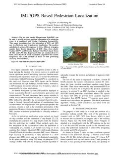
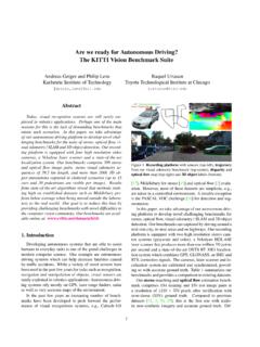
4 The data sheet for any accelerometer will denote the positive x, y, and z axes on the sensor package and, by convention, these are defined so that a Linear acceleration aligned in the direction of these axes will give a positive accelerometer gravitational field component aligned along the same axes directions will, however, result in a negative reading on the accelerometer. This can be understood by looking at an electron microscope image of a MEMS accelerometer. The upper proof mass is suspended by the restoring springs. Both a gravitational field directed to the left and a Linear acceleration of the package to the right will deflect the proof mass to the left. Figure 1. Electron Microscope Image of MEMS Accelerometer Proof Mass and Sensing PlatesThe deflection of the proof mass is measured from the change in capacitance between the fingers of the proof mass and the Sensing plates. A simplified transducer model and equivalent electrical circuit are shown in Figure 2.
5 Circuitry internal to the accelerometer sensor converts the tiny capacitance to a voltage signal which, in digital Accelerometers , is then digitized and output as a digital word over a serial Proof Mass with fingersRestoring springsSensing platesTilt Sensing Using a Three-Axis Accelerometer, Rev. 64 Freescale Semiconductor, Inc. Figure 2. Simplified Transducer Model and Equivalent Electrical CircuitThe 'native' coordinate system of the accelerometer is not a convenient system to use when discussing the orientation of a consumer product, such as a smartphone, since the accelerometer can be mounted at any orientation on the circuit board which can, in turn, be mounted at an arbitrary angle in the final product. It is more sensible to use a coordinate system aligned with the smartphone product axes. Figure 3 shows the coordinate system which will be used in this document: The x-axis is aligned along the body axis of the smartphone The z-axis points downwards so that it is aligned with gravity when the smartphone is flat on a table The y-axis is aligned at right angles to both the x and z axes so that the three axes form a right handed coordinate in orientation are described by rotations in roll , pitch and yaw about the x, y and z axes MassSimplified ModelEquivalent CircuitTilt Sensing Using a Three-Axis Accelerometer, Rev.
6 6 Freescale Semiconductor, Figure 3. Definition of Coordinate System and Rotation AxesIn addition, since this document is concerned with measuring orientation in the earth's gravitational field, the convention will be adopted that the accelerometer output is negated to give value +1g in any axis aligned with the earth's downward gravitational this assumption, a three-axis accelerometer mounted in a smartphone oriented in the earth's gravitational field g and undergoing Linear acceleration ar measured in the earth's reference frame r, will have output Gp given by:Eqn. 1where R is the rotation matrix describing the orientation of the smartphone relative to the earth s coordinate axisRoll Pitch Ya w GpGpxGpyGpz Rg ar ()== tilt Sensing Using a Three-Axis Accelerometer, Rev. 66 Freescale Semiconductor, Inc. It is further assumed that: The accelerometer has no Linear acceleration . This assumption is needed to solve Equation 1 for the rotation matrix R and, in consequence, any Linear acceleration from handshake or other sources will introduce errors into the orientation estimate.
7 The initial orientation of the smartphone is lying flat with the earth's gravitational field aligned with the smartphone z-axis:With these additional assumptions, the smartphone accelerometer output Gp (measured in the native accelerometer units of g) is:Eqn. 2 The next section introduces the components of the rotation matrix R and describes how to determine the roll and pitch angles from the accelerometer and Roll EstimationThe orientation of the smartphone can be defined by its roll, pitch and yaw rotations from an initial position . The roll, pitch and yaw rotation matrices, which transform a vector (such as the earth's gravitational field vector g) under a rotation of the coordinate system of Figure 3 by angles in roll, in pitch and in yaw about the x, y and z axes respectively, are: Eqn. 3 Eqn. 4 Eqn. 5 There are six possible orderings of these three rotation matrices and, in principle, all are equally valid.
8 The rotation matrices do not, however, commute meaning that the composite rotation matrix R depends on the order in which the roll, pitch and yaw rotations are applied. It is instructive to compute the values of the six possible composite rotation matrices R and to determine their effect on the earth's gravitational field of 1g initially aligned downwards along the GpGpxGpyGpz RgR001 ===Rx ()10 00 cos sin0 sin cos =Ry () cos0 sin 01 0 sin0 cos =Rz () cos sin0 sin cos0001 = tilt Sensing Using a Three-Axis Accelerometer, Rev. 6 Freescale Semiconductor, Eqn. 6 Eqn. 7 Eqn. 8 Eqn. 9 Eqn. 10 Eqn. 11 Eqn. 12 Eqn. 13 Rxyz001 Rx ()Ry ()Rz ()001 = coscos sincos sin sincos sinsincos coscos sinsinsin+ sincos sinsin+sincoscos sinsincos sincos coscos 001 = sin sincos coscos =Ryxz001 Ry ()Rx ()Rz ()001 = coscos sinsinsin sin cos cossinsin+ cossin sincos coscos sin cossin+sinsincos sincoscos sinsin+ coscos 001 = cossin sin coscos =Rxzy001 Rx ()Rz ()Ry ()001 = cos cos sin sincos sincoscos sinsin+ coscos sincos sinsincos+ sincos+sinsincos sincos coscos sinsinsin 001 = tilt Sensing Using a Three-Axis Accelerometer, Rev.
9 68 Freescale Semiconductor, Inc. Eqn. 14 Eqn. 15 Eqn. 16 Eqn. 17 Eqn. 18 Eqn. 19 Eqn. 20 sincos sincos sinsincos+ coscos sinsinsin =Ryzx001 Ry ()Rz ()Rx ()001 = coscos sinsin+sincoscos cossin sinsincos sin coscos sincos sincos sincos sinsincos+ coscos sinsinsin+ 001 = sinsincos sincos sincos coscos sinsinsin+ =Rzxy001 Rz ()Rx ()Ry ()001 = coscos sinsinsin+ sincos cossin sinsincos sincos sinsincos+ coscos sincoscos sinsin+ sincos sin coscos 001 = cos sinsin cos sin cos sinsin+sincos coscos = tilt Sensing Using a Three-Axis Accelerometer, Rev. 6 Freescale Semiconductor, Eqn. 21 Eqn. 22 Eqn. 23It can be readily seen from Equations 6 to 23 that the six composite rotation matrices and the six values of the measured gravitational vector are all different.
10 A consequence is that roll, pitch and yaw rotation angles are meaningless without first defining the order in which these rotations are to be of these rotation sequences can be immediately rejected as being unsuitable for determining the smartphone orientation . The accelerometer output has three components but, since the vector magnitude must always equal 1g in the absence of Linear acceleration, has just two degrees of freedom. The accelerometer vector lies on the surface of a sphere with radius 1g. It is not therefore possible to solve for three unique values of the roll , pitch and yaw angles. The four rotation sequences in Equations 12 to 23 result in the accelerometer output being a function of all three rotation angles and cannot therefore be contrast, the two rotation sequences in Equations 6 to 11 depend only on the roll and pitch angles and can be solved. The lack of any dependence on the yaw rotation angle is easy to understand physically since the first rotation is in yaw around the smartphone z-axis which is initially aligned with the gravitational field and pointing downwards.