Transcription of AUTOPILOT CONTROL SYSTEM - idc-online.com
1 AUTOPILOT CONTROL SYSTEM ABSTRACT An AUTOPILOT is a mechanical, electrical, or hydraulic SYSTEM used to guide an aerial vehicle without assistance from a human being. It also maintains the orientation of the plane by monitoring the relevant flight data from inertial measurement instruments and then using that data to cause corrective actions. In this project an attempt has been made to design, implement and develop an AUTOPILOT for a glider plane. 3-axis accelerometer and gyroscopes are used to input the acceleration and tilt data into the controller. This data is then used for further estimation and fuzzy logic is implemented for decision making. The required corrective measures are affected by a set of servo motors which helps the flight path and orientation to be maintained at the desired levels.
2 INTRODUCTION Overview: In the early days of aviation, aircraft required the continuous attention of a pilot in order to fly safely. As aircraft range increased allowing flights of many hours, the constant attention led to serious fatigue. An AUTOPILOT is designed to perform some of the tasks of the pilot. Along the flight path the vehicle is under the influence of various accelerating forces in all directions and these factors cause it to deviate from its desired path. So the plane loses its heading as well as orientation . This is where AUTOPILOT comes into picture. There are three levels of CONTROL in autopilots for smaller aircrafts. A single-axis AUTOPILOT controls an aircraft in the roll axis only. A two-axis AUTOPILOT controls an aircraft in the pitch axis as well as roll axis with pitch-oscillation-correcting ability.
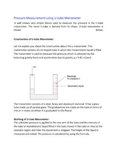
3 A three-axis AUTOPILOT adds CONTROL in the yaw axis and is not required in many small aircraft. The 3 different axes mentioned are shown in Fig The flight may also receive inputs from on-board radio navigation systems to provide true automatic flight guidance once the aircraft has taken off until shortly before landing. Fig - Angles of Rotation History: The first aircraft AUTOPILOT was developed by Sperry Corporation in 1912. Lawrence Sperry demonstrated it two years later in 1914, and proved the credibility of the invention by flying the aircraft with his hands away from the controls and visible to onlookers. The AUTOPILOT connected a gyroscopic heading indicator and attitude indicator to hydraulically operated elevators and rudders. It permitted the aircraft to fly straight and level on a compass course without a pilot's attention, greatly reducing the pilot's workload.
4 The AUTOPILOT CONTROL systems have evolved drastically since the turn of the century. Modern autopilots use computer software to CONTROL the aircraft. The software reads the aircraft's current position , and controls a flight CONTROL SYSTEM to guide the aircraft. In such a SYSTEM , besides classic flight controls, many autopilots incorporate thrust CONTROL capabilities that can CONTROL throttles to optimize the air-speed, and move fuel to different tanks to balance the aircraft in an optimal attitude in the air. Although autopilots handle new or dangerous situations inflexibly, they generally fly an aircraft with a lower fuel-consumption than a human pilot. Problem Defination The basic objective of our project is to design and develop an auto pilot CONTROL SYSTEM which can maintain the desired orientation of the glider.
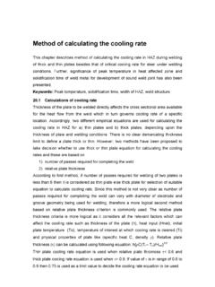
5 The acceleration data in all 3 axes are obtained by the combination of accelerometer and gyroscopes and the angles of roll, pitch and yaw are calculated. These values are taken for estimation using a Kalman filter and the resulting values helps us in the decision making. The flight is kept in its path and desired orientation with the help of servo motors. The basic SYSTEM as shown in Fig comprises of an input block, a controller block and an actuator block. The input measures the angular velocity and acceleration of the setup. A 3-axis accelerometer axis used which gives precise acceleration measurements along the 3 axes. These acceleration values are later used to obtain the angular tilt along the 3 directions. Also 3 different gyroscopes are used for the angular measurements in the 3 different axes.
6 A combination of the values from the accelerometer and gyroscopes are used and different weightages are given these 2 sets of values. The microcontroller used is ATMEGA32. The input data is taken to the controller ADC modules. It is then passed to the Kalman filter for estimation . The estimated values are further taken to the fuzzy controller unit where the magnitude change from the desired orientation is used for the decision making. The servo motor interfacing unit decides the amount of rotation of the servos to help the flight maintain the desired orientation . The controller also includes the LCD interfacing unit, the memory card interfacing unit and the computer interfacing unit. The interfacing units are for transferring the log data into the computer and memory card. The data is taken into the computer for calibration of the input devices.
7 The in-flight data is continuously logged into the memory card on board. An LCD panel is used for displaying the angle values. The actuator unit is the set of servo motors used for affecting the change in direction of the glider. Fig - Block Diagram INERTIAL MEASUREMENT UNIT An inertial measurement unit, or IMU, is the main component of inertial guidance systems used in air, space, and watercraft, including guided missiles. They measure inertial acceleration, also known as G-forces. An IMU works by sensing motion including the type, rate, and direction of that motion using a combination of accelerometers and gyroscopes. The data collected from these sensors allows a computer to track a craft's position , using the method known as dead reckoning. An IMU works by detecting the current rate of acceleration, as well as changes in rotational attributes, including pitch, roll and yaw.
8 This data is then fed into a computer or a microcontroller, which calculates the current speed and position , given a known initial speed and position . A major disadvantage of IMUs is that they typically suffer from accumulated error. Because the guidance SYSTEM is continually adding detected changes to its previously-calculated positions, any errors in measurement, however small, are accumulated from point to point. This leads to 'drift', or an ever-increasing difference between where the SYSTEM thinks it is located, and the actual location. The IMU of our AUTOPILOT SYSTEM includes a 3-axis accelerometer along with 3 gyroscopes. A combination of values from these devices is used as input. An accelerometer measures the acceleration it experiences relative to freefall. Single- and multi-axis models are available to detect magnitude and direction of the acceleration as a vector quantity, and can be used to sense orientation , vibration and shock.
9 This measurement is equivalent to inertial acceleration minus the local gravitational acceleration, where inertial acceleration is understood in the Newtonian sense of acceleration with respect to a fixed reference frame, which the Earth is often considered to approximate. For the purpose of finding the acceleration of objects knowledge of local gravity is required. This can be obtained either by calibrating the device at rest, or from a known model of gravity at the approximate current position . We are calibrating the accelerometer by taking sample readings at rest and then finding the error offset. Conceptually, an accelerometer behaves as a damped mass on a spring. When the accelerometer experiences an external force such as gravity, the mass is displaced until the external force is balanced by the spring force.
10 The displacement is translated into acceleration. The accelerometer we have used in our project is based on micro electro-mechanical systems (MEMS). These chips are the simplest MEMS devices possible, consisting of little more than a cantilever beam with a proof mass (also known as seismic mass). Under the influence of external accelerations the proof mass deflects from its neutral position . This deflection is measured in an analog or digital manner. Most commonly, the capacitance between a set of fixed beams and a set of beams attached to the proof mass is measured. 3 such devices are integrated perpendicularly to form the 3-axis accelerometer. The accelerometer we have used for this project is from Freescale Semiconductors. It is a MEMS device which gives an analog voltage output proportional to accelerations along its different axis.