Transcription of IMU/GPS based pedestrian localization
1 2012 4th Computer Science and Electronic Engineering Conference (CEEC) University of Essex, UK. IMU/GPS based pedestrian localization Ling Chen and Huosheng Hu School of Computer Science and Electronic Engineering University of Essex, Colchester CO4 3SQ, United Kingdom E-mail: {lcheno, Abstract The low cost Inertial Measurement Unit(IMU) can be used to provide accurate position information of a pedestrian . when it is combined with Global Positioning System(GPS). This paper investigates how the integration of IMU anf GPS.}
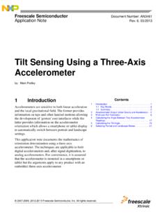
2 Can be effectively used in pedestrian localization . The position calculation is achieved in sequence by three different strategies, namely basic double integration of IMU data, Zero-velocity Update (ZUPT) and Extended Kalman Filter(EKF) based fusion . of IMU and GPS data. Experiments that are conducted in two elds show that EKF based localization outperform the double integration and ZUPT methods in terms of both positioning accuracy and robustness. Keywords-IMU;GPS; localization ;ZUPT;EKF. (a) Foot Mounted IMU (b) GPS Receiver I.
3 I NTRODUCTION Fig. 1. Placement of IMU and GPS receiver module. (a) Foot-Mounted IMU;. (b) GPS Module It is highly demanded that a navigation system is able to keep tracking the location of a person, such as in search and rescue operations, as well as training exercises, location-aware optimally estimate the position and attitude of a person while computing and augmented reality [1]. To realize the pedestrian walking. localization , Global Positioning System(GPS) is considered as The rest of the paper is organized as follows.
4 Section II. the main tool. However, since GPS signals can be blocked brie y presents the system con guration. Section III intro- and in uenced by high buildings, human bodies, mountains, duces the basic position calculation equation using Xsens a GPS normally has errors between 1 to 10 meters, which is Mti IMU. Then error correction by stop detection(ZUPT) is unacceptable for some applications. discussed in Section IV to improve the position calculation An Inertial Navigation System(INS) could be deployed to accuracy.
5 In section V, an EKF algorithm is applied to the locate a pedestrian based on accelerometers, gyroscopes and IMU/GPS based pedestrian localization , where GPS signals magnetometers. The unit integrating these sensors together is are fused with IMU to provide more accurate trajectory called Inertial Measurement Unit(IMU). As opposed to GPS, information than ZUPT. Section VI presents some experi- IMU will not be affected by the environment where the pedes- mental results to validate the proposed IMU/GPS localization trian is located.
6 Integral calculations of accelerations from algorithm. Finally, a brief conclusion and future work are accelerometers and angular rates from gyroscopes produce the presented in Section VII. position , velocity as well as the orientation information of the pedestrian . However, the mean-squared navigation errors of an II. S YSTEM C ONFIGURATION. IMU increase with time quadratically or cubically without a The purpose of this study is to track the position of a boundary. pedestrian walking outside. One foot of the pedestrian is As for the pedestrian localization , some methods are based mounted with an IMU (MTi from Xsens), which is used on step counters and the estimation of step length [2], [3], to measure the acceleration and angular rate of the walking multiplying the counters by a step length yields the distance foot(see Figure 1a).
7 The GPS module (from Phidgets) is that the pedestrian has walked. Other methods apply dou- attached to a straight pole with the GPS antenna on the top ble integration of the accelerations when the pedestrian is of it so that the GPS position signal can be obtained more walking [4], [5]. Jimenez et. al [6]and Isaac Skog et. al [7] easily. The pedestrian localization is achieved by integrating combine Zero-Velocity Update(ZUPT) with Extended Kalman the inertial and GPS information. Filter(EKF) which is used to correct the IMU errors.
8 However, As shown in Figure 2, there are two coordinate systems high accuracy of positioning is only achieved in a short involved in the pedestrian tracking: 1) Inertial sensor body distance since IMU errors can not be eliminated completely. frame (B); 2) The global reference frame (W ) whose X-Y. In this paper, instead of using IMU alone, we integrate ZUPT plane is parallel with the earth surface with X axis pointing to strategy of IMU with GPS by designing an EKF algorithm to the East, Y axis pointing to the North and Z axis pointing to 978-1-4673-2666-7/12/$ 2012to:IEEE.
9 Authorized licensed use limited 2302,2020 at 02:37:37 UTC from IEEE Xplore. Restrictions apply. Tencent. Downloaded on July 2012 4th Computer Science and Electronic Engineering Conference (CEEC) University of Essex, UK. As analyzed above, the useful acceleration data is the foot =: accelerations in reference frame W , which are represented as aW. k . It is calculated from the inertial measurements using =%.. aW B. k = Q k ak Q k G (2). where * is the quaternion multiplication. G = (0, 0, g)T. 2% represents the earth gravity.
10 Qk = (qw,k , q1,k , q2,k , q3,k ) is ;%. a quaternion representation of the rotation transformation <% between the inertial sensor frame B and the global reference frame W . The acceleration measured by the inertial sensor 2: <: aBk includes the acceleration caused by a speci c force and gravity. After transforming the acceleration into frame W and . subtracting the gravity, the aWk represents the acceleration 5%: caused by the speci c force only imposed on the target. There is a transformation formula between quaternion and Euler Angle, which is represented as follows.