Transcription of AVR241: Direct driving of LCD display using …
1 avr241 : Direct driving of LCD display using general IO Features Software driver for displays with one common line Suitable for parts without on-chip hardware for LCD driving Control up to 15 segments using 16 IO lines Fully interrupt driven operation Introduction As a low power alternative to LEDs and 7-segment LED-displays, small Liquid Crystal Displays (LCD) with only a limited number of segments are becoming more and more popular. Due to complex driving waveforms, interfacing to LCDs has traditionally been done via a hardware driver either integrated in the LCD or MCU. But as the complexity of the waveform is dependent on the number of back planes in the LCD, these small LCDs with few common lines are less complex and software interfaces can be suitable.
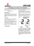
2 This application note describes software driving of LCDs with one common line, using the static driving method. Figure 1. An AVR driving a LCD display directly, using general IO. AVR 8-bit Microcontrollers Application Note Rev. 2569A-AVR-04/04 2 avr241 2569A-AVR-04/04 Theory of operation This section provides an overview of common features and a introduction to terminology used in relation to LCD glass. Theory will focus upon driving of LCD glass with one common line. This section describes the terminology used throughout this document. One of the bars/dots in a LCD display , controlled individually. A frame is equivalent to one period of the cyclic waveform that is written to a segment. Figure 2 gives a further explanation of what a frame is.
3 Frame rate is the number of frames per second. The frame rate should normally be kept high enough to avoid that the human eye perceives the segments as flickering and low enough to avoid ghosting. Ghosting occurs when segments are energized due to cross talk between segment lines. The frame rate should normally be kept between 30 and 100 Hz. Electrical connection terminal shared by all display segments. Electrical connection terminal connected to a single segment. The LCD is based upon a display technology that uses rod-shaped molecules (liquid crystals) that flow like liquid and bend light. Non-energized, the crystals Direct light through two polarization filters, allowing a natural background color to show, making it invisible.
4 When energized, they redirect the light to be absorbed in one of the polarizers, causing the dark appearance making it visible. The smallest viewing element that can be turned visible/invisible (energized/non-energized) is referred to as a display segment. Each display segment has two connection terminals. One terminal is connected to a segment driver and the other to a common terminal. One common terminal is shared by a number of segments. Applying a voltage between the common terminal and a segment terminal energizes the segment. Additionally the segment voltage has to be alternated. DC ( Direct current) will cause electrophoresis effects in the liquid crystal and will degrade the display . Consequently the voltages on both the common terminal and the segment terminals must alter.
5 There are basically two driving methods for displays: Static and multiplexed. In the multiplexed driving method many displays share segment lines, and the controlling of several common lines multiplexes the displays. This method will need a variety of complex waveforms and multiple analog levels to be sent to the display . In the static driving method only one common line is used and each display segment will have their unique terminal. This method will need relatively simple waveforms applied to terminals. However, the static driving method is not suitable for LCDs with many segments since each segment will need one dedicated output-pin from the MCU. For more LCD theory please refer to application note AVR065: LCD Driver for the STK502 and AVR Butterfly.
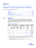
6 This application note will use the static driving method. Figure 2 shows energized and non-energized segments and their driving waveforms. Terminology used in relation to LCD Segment Frame Frame rate Common line Segment line LCD glass avr241 32569A-AVR-04/04 Figure 2. 2 segments connected to 1 common terminal. Common lineSegment line 1 Segment line 0 Non-energizedsegmentEnergizedsegmentSeg0 Seg1 VlcdGndGndVlcdVlcdGnd-VlcdFrameFrameSeg 0 ComSeg 0 -ComVlcdGndGndVlcdVlcdGnd-VlcdFrameFrame Seg 1 ComSeg 1 -Com 4 avr241 2569A-AVR-04/04 Figure 3 shows a simplified equivalent circuit for a LCD. For a RC network like this the main power consumption will occur in the region where the input waveforms are toggling due to increased current through C1 and C2, hence lowering the LCD frame rate will decrease the power consumption.
7 In general the frame rate should be kept above 30Hz to avoid display flickering. Though, in low power applications ( battery applications) the frame rate could be less than 30Hz as long as the display contrast/flickering is satisfying for the given application. R1: Segment- and common-plane resistance. R2: Liquid crystal resistance. C1: Barrier- and alignment-layer capacitance. C2: Liquid crystal capacitance. Figure 3. Simplified LCD equivalent circuit. R2 Segment lineCommon lineC1C2R1 Power consumption avr241 52569A-AVR-04/04 Implementation This section contains a description on how to connect a LCD to the AVR and how the software should be implemented. The application can be tested directly on a STK500 with a single-common LCD connected. Program code is written in C for the IAR EWAVR v.
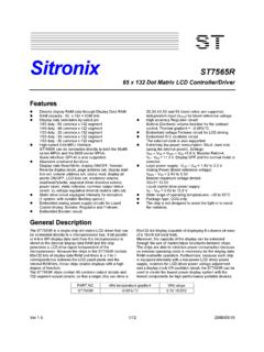
8 , but other compilers can be used with only minor changes of the code. This application note is made with an ATmega16, but any AVR microcontroller with sufficient number of IO pins may be used. The software is tested with a LCD type S5080D from Clover display . The application describes driving of 15 segments forming a 2x7-segment display + 1 dot segment as shown in figure 2. Controlling of all 15 segments and the common line requires 16 I/O pins. This number can be reduced in applications where a lower number of LCD-segments are required. Software contains functions for easy writing of data to the LCD. Figure 4. Physical connection of a 2x7+1 segment LCD. Dot -segment on digit 1 is not connected. DIG1 DIG21abcdefg1abcdefgAVRPD0:PD6 DIG1A:DIG1 GPB0:PB6 DIG2A:DIG2 GPB7 DOT2PD7 COMLCDDOT2 VCCGND Physical connection 6 avr241 2569A-AVR-04/04 The LCD driver software is interrupt driven and suitable for use in low power applications.
9 The software consists of the function LCD_print() which is the driver interface and the function LCD_update() which is used by the driver to write to the LCD. Including the driver in an existing application is done as follows: 1. Add to the project and to the include files. 2. Set up a timer interrupt as described in section below. 3. Call the function LCD_update() once for each timer interrupt. 4. Print to LCD by using the function LCD_print(). shows an implementation of this application on an ATmega16 running from the internal 1 Mhz RC-oscillator. Table 1. LCD driver C function description. Function Arguments Return LCD_print(global) Unsigned char digit, Unsigned char ASCII_data Unsigned char LCD_print() is used by the main application to prepare data for LCD_update().
10 The function receives ASCII values for the LCD to display , converts it to segment patterns and initiates a LCD update. Input arguments for LCD_print describe what digit to access (char digit) and what ASCII value (char ASCII_data) to output on the digit. The digit number to access should be in the range [1,2]. Figure 4 shows the digit numbering. The ASCII input needs to follow certain rules to match the LCD: 5. Bit 0:6 should contain a 7-bit ASCII code in the range given by Table 2. 6. Bit 7 turns the LCD dot -segment on/off. Bit 7 = 1 turns dot -segment ON and bit 7 = 0 turns dot -segment OFF. Notice that only dot -segment for digit 2 can be written. ASCI_data:7 should always be 0 when printing to digit 1. The functions return value is 1 for success and 0 for failure.