Transcription of AXE133Y SERIAL OLED - Home - PICAXE
1 AXE133Y SERIAL OLEDAXE132 SERIAL Driver Kit(no display supplied)AXE133 YSerial OLED Kit(16x2 yellow on black OLED display)AXE133 SERIAL LCD Kit(16x2 budget grey LCD display)AXE134 YSerial OLED Kit(20x4 yellow on black OLED display)Introduction:The SERIAL OLED/LCD module allows PICAXE microcontroller projects tovisually display user instructions or sensor readings. All commands aretransmitted serially via a single microcontroller pin using the seroutcommand. to print the text Hello the command is simply:serout ,N2400,( Hello )Key Features:1. 16x2 or 20x4 OLED or LCD Alphanumeric Display2. Simple SERIAL connection to PICAXE microcontroller (baud 2400,N,8,1).
2 3. Open source firmware based upon a PICAXE -18M2 microcontroller, with option to re-program and store up to 16 pre-defined Contents:PCB1 AXE133 PCBD isplay116x2 OLED or 16x2 LCD or 20x4 OLEDIC11 PICAXE -18M2 preprogrammed with AXE133 firmwareIC1118 pin IC socketR1122k resistor(red red orange gold)R2,3210k resistor(brown black red gold)C11100nF download socketH1,2210 pin header (snap to length as required)VR1110k preset (not required for OLED kits - LCD Contrast)Kit Assembly:1. Solder the 2x10k and 1x22k resistors onto the PCB (values are marked on the PCB).2. Solder the capacitor C1 and 18 pin IC socket IC1 into position.
3 Insert the PICAXE -18M2 microntroller into the socket, ensuring pin 1 is furthest from the Click the socket into position CON1, ensure it is lying flat on the PCB andthen solder into position. The two pairs of pins are connected, so do not worryabout solder bridges on those two pairs of kits only (not required for OLED kits) - Solder the 10k preset resistor in positionVR1. This is used to adjust the contrast of the LCD Snap one ten way header into a 4 way and 3 way section. Solder the 3 pin sectionon the top of the PCB in position HEADER HI IS FITTED UNDERNEATH THE BOARD. Use the 10 way and 4way headers to create the OLED/LCD header H1.
4 Note this connector is solderedunderneath the board (so that the solder joints are on the top side of the board).9. Double check all solder joints on the PCB to ensure they are correctly soldered andtrimmed short. It is not possible to adjust them once the OLED/LCD has beenfitted, so carefully check then Place the OLED/LCD display onto header H1, maintaining a few mm gap betweenthe solder joints and the back of the LCD. Solder one header pin in place, adjustclearance as required by reheating this pin, then solder all the other the full datasheet please see: copyright 2011 Revolution Education SERIAL OLED / SERIAL LCDrevolution copyright 2011 Revolution Education Ltd.
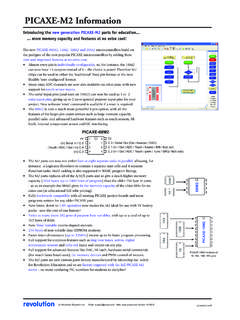
5 / Output / Power ConnectionsMain Header H2 (IN, V+,0V)The main header provides connection for the power supply ( or 5V DC on V+).The pin marked IN connects directly to the controlling PICAXE output pin. Do notconnect via a Darlington driver buffered output on a project board - always connectdirectly to the PICAXE pin. This H2 header has been designed to be compatiblewith the popular servo extension lead Header H3 This header provides connection points to the unused i/o pins ( , , ) andpower. These may be used as general purpose outputs, or any other purpose byreprogramming the AXE133 firmware. in the PICAXE -18M2 PICAXE Programming Connector CON1 This PICAXE programming connector allows the PICAXE -18M2 to bereprogrammed ( to update the AXE133 firmware).
6 The default AXE133 programis available via the PICAXE website the SERIAL OLED/LCD to a PICAXE MicrocontrollerThe following diagram shows how to connect the SERIAL OLED/LCD module to thePICAXE system via header H2. Connect directly to the PICAXE output Test programinit:pause 500 ; wait for display to initialisemain:serout ,N2400,(254,128) ; move to start of first lineserout ,N2400,( Hello!123 ) ; output textendDisplaying MessagesThe LCD can display characters and pre-defined messages, and can also acceptcertain control commands ( clear display or move cursor to new position). Notethat the SERIAL LCD module takes approx half a second to initialise and so any datasent during this period will be lost.
7 It is advisable to put a pause 500 command atthe start of any program to ensure no data is lost when the system is powered up. 318M2 SERIAL OLED / SERIAL LCDrevolution copyright 2011 Revolution Education Ltd. are normal symbols that can be displayed on the OLED/LCD screen. SeeAppendix 1 for a table of the common ASCII characters (values 0-252).serout ,N2400,( Hello!123 ) ; output textCharacters (0-252) can be described via two methods in the serout command either by using the ASCII number directly or the character enclosed in speech (65) and ( A ) both output the same that the numbers 253, 254 and 255 are used for special purposes:253 MessageNext byte is a predefined message (0-15)254 ControlNext byte is a control command255 OutputNext byte controls outputs , , Commands (253)Predefined messages are all prefixed by the number 253.
8 There are up to 16 (0-15)predefined messages, all stored within the AXE133 firmware program. To reprogramthe messages simply reprogram the PICAXE -18M2 ,N2400,(254,128) ; move to start of first lineserout ,N2400,(253,1) ; display predefined message 1pause 10 ; allow message to updateControl Commands (254)Control commands are all prefixed by the number 254. They are used to sendcommands to the SERIAL LCD Module ( move to line 2, switch cursor off etc.).serout ,N2400,(254,192) ; move to start of second lineThe most common control commands are254,1 Clear Display (must be followed by a pause 30 command)254,8 Hide Display254,12 Restore Display254,14 Turn on Cursor254,16 Move Cursor Left254,20 Move Cursor Right254,128 Move to line 1, position 1254, yMove to line 1, position x (where y = 128 + x)254,192 Move to line 2, position 1254, yMove to line 2, position x (where y = 192 + x)For a table of all available command codes please see the control command table inthe OLED/LCD datasheet Command (255)
9 Outputs , and are all controlled by the lower 3 bits of an output byte,which is prefixed by the number ,N2400,(255,%00000111) ; all outputs onpause 1000serout ,N2400,(255,%00000000) ; all outputs off418M2 SERIAL OLED / SERIAL LCDrevolution copyright 2011 Revolution Education Ltd. A - OLED Character Table WS0010 WESTERN EUROPEAN CHARACTER FONT TABLE I (FT[1:0]=01) 518M2 SERIAL OLED / SERIAL LCDrevolution copyright 2011 Revolution Education Ltd. ! " # $ % $ # # # # & '" #( )) **&+, # # # # " # - " # Appendix B - Circuit Diagram