Transcription of PICAXE Manual www.picaxe
1 PICAXE !This PDF is designed to be used with the shortcut links (document outline) visible on the lefthand side. Displaying these links makes it much easier to navigate through this Manual ! section 1 GETTING STARTED revolution(c) Revolution Education : rights 10 this Manual .. 4 Software Overview .. 4 Software Comparison .. 5 Software Quick Choice Guide .. 5 Third Party Software .. 5 Technical Support Forum .. 5 Quick Start - Project Board PCB Preparation .. 6 Quick Start - Flashing an LED .. 7At a glance - specifications: .. 8At a glance - download circuit: .. 8At a glance - pinout diagrams (older parts): .. 9At a glance - pinout diagrams (M2 parts): .. 10At a glance - pinout diagrams (X2 parts): .. 11 What is a microcontroller? .. 12 Microcontrollers, input and outputs .. 13 What is the PICAXE system?.. 14 Building your own circuit / PCB .. 14 What is a PICAXE microcontroller? .. 15 PICAXE chip labels.
2 16 Superseded older PICAXE chips .. 16 Which PICAXE chip? .. 17 Using the PICAXE system.. 19 PICAXE Starter Packs .. 20 PICAXE Project Boards .. 21 Software Installation .. 22 Installation on RM CC3 networks .. 22 Installing the AXE027 USB cable drivers .. 23 Downloading over a network using TCP/IP .. 24 PICAXE Power Supply .. 25 PICAXE -08M2/08M/08 Pinout and Circuit .. 27 PICAXE -14M2/14M Pinout and Circuit .. 28 PICAXE -20X2/20M2/20M Pinout and Circuit .. 30 PICAXE -18M2/18X/18M/18A/18 Pinout and Circuit .. 32 PICAXE -28X2/28X1/28X/28A Pinout and Circuit .. 34 PICAXE -28X2 Module (AXE200/AXE201).. 36 PICAXE -28X2 Shield Base (AXE401).. 38 PICAXE -40X2/40X1/40X Pinout and Circuit .. 40 USB Download Circuit .. 43 Serial Download Circuit (NB: Obsolete, for info only) .. 44 Enhanced Serial Download Circuit (NB: Obsolete, for info only) .. 45 Download Cables .. 45 Using the Serial In pin as a general input pin.
3 46 Reset Circuit .. 47 Testing the System .. 49 Hard-reset procedure .. 50 Download Checklist .. 51 Understanding the PICAXE memory.. 52 Parallel Task Processing .. 62 Flowchart or BASIC? .. 66 BASIC Simulation .. 67 Interfacing Circuit Summary .. 70 Tutorial 1 Understanding and using the PICAXE System .. 71 Input / Output Pin Naming Conventions .. 72 Tutorial 2 - Using Symbols, Comments & White-space .. 75 Tutorial 3 - Loops .. 76 Tutorial 4 - Making Sounds .. 77 Tutorial 5 Using Digital Inputs .. 78 Tutorial 6 Using Analogue Sensors .. 79 Tutorial 7 - Using Debug .. 80 Tutorial 8 - Using Serial Terminal with Sertxd .. 81 Tutorial 9 - Number Systems .. 82 Tutorial 10 - Sub-procedures .. 84 Tutorial 11 - Using Interrupts .. 86 section 1 GETTING STARTED revolution(c) Revolution Education : rights 10 next step - your own PICAXE project! .. 89 Appendix A BASIC Commands Summary .. 90 Appendix B Over-clocking at higher frequencies.
4 91 Appendix C Configuring the obsolete PICAXE -14M I/O Pins .. 93 Appendix D Configuring the obsolete 08/08M I/O Pins .. 95 Appendix E Configuring the obsolete 28X/28X1 I/O Pins .. 97 Appendix F Configuring the obsolete 40X/40X1 I/O Pins .. 99 Appendix G - Frequently Asked Questions (FAQ).. 101 Appendix I - Advanced Technical Information and FAQ .. 105 Software Version .. 110 Contact Address .. 110 Acknowledgements .. 110 section 1 GETTING STARTED revolution(c) Revolution Education : rights 10 this manualThe PICAXE Manual is divided into four separate sections: section 1 -Getting Started( ) section 2 -BASIC Commands( ) section 3 -Microcontroller interfacing circuits ( ) section 4 -Using Flowcharts( )This first section provides general information for getting started with the PICAXE system. No prior understanding of microcontrollers is required. A series oftutorials introduce the main features of the more specific information, syntax and examples of each BASIC Commandplease see section 2 BASIC Commands.
5 For microcontroller interfacing circuits, and example programs, for mostcommon input/output transducers, please see section 3 Software OverviewRevolution Education Ltd publish 3 software titles for use with the PICAXE microcontroller chips. Two are free, the other two are low cost Editor 6 The PICAXE Editor is the main Windows application used for programmingPICAXE chips. This software is free of charge to PICAXE PICAXE Editor supports both textual (BASIC) and flowchart (graphical)methods of developing programs. This Manual was prepared using version the PICAXE Editor is a simpler, free version of the PICAXE Editor software for use on theLinux and Mac operating systems. It supports the BASIC programming VSMPICAXE VSM is a full Berkeley SPICE circuit simulator, which will simulatecomplete electronic circuits using PICAXE chips. The BASIC program can bestepped through line by line whilst watching the input/output peripheral react tothe Manual focuses on the BASIC textual programming language, as used by PICAXEE ditor, AXEpad and PICAXE see part 4 of the Manual for more details about the flowchart 1 GETTING STARTED revolution(c) Revolution Education : rights 10 ComparisonKey:X= Supported(X)= Supported, but more suitable product also available,Software Quick Choice GuideWindows-> Textual BASIC programming-> PICAXE Editor-> Flowchart programming-> PICAXE Editor-> SPICE Circuit Simulation-> PICAXE VSMMac-> Textual BASIC programming-> AXEpadLinux-> Textual BASIC programming-> AXEpadThird Party SoftwareRevolution produce royalty free PICAXE drivers that can be used to add PICAXE support to third party products.
6 Current third party software products include:Win/Mac/Linux-> Flowchart programming-> Yenka PICs->Circuit Simulation-> Yenka Electronics->PCB Artwork-> Yenka PCB-> Flowchart programming-> FlowolTechnical Support ForumIf you have a question about any aspect of the PICAXE system please post aquestion on the very active (and friendly!) support forum at this EditorAXEpadPICAXE VSMBASIC programming optionXXXF lowchart programming optionXAssembler code outputXWindows VersionX(X)XLinux VersionXMac OSX VersionXOn Screen SimulationXXBerkeley SPICE Circuit SimulationXSupport of all PICAXE TypesXXXCost / DistributionFreeFreeCost Option( 50) section 1 GETTING STARTED revolution(c) Revolution Education : rights 10 Start - Project Board PCB PreparationMany Revolution Education project boards, as supplied in the starter packs, aresupplied with a protective peelable layer over the user solder pads on the rear ofthe PCB.
7 This layer may be red or green in colour and can be easily peeled offwith your finger nail before peelable layer protects the user solderable pads during manufacture andstorage, to keep the pads clean and grease also that the solder pads on our PCBs may be a dull white milky colour,not shiny silver as in the past. This is due to the more environmentallyfriendly lead-free chemicals now used for plating RoHS compliant is not a fault and the pad can still be hand soldered just as easily as the olderstyle shiny solder pads. No cleaning is generally required prior to project board, as suppliedin the PICAXE -18 Starter 1 GETTING STARTED revolution(c) Revolution Education : rights 10 Start - Flashing an LEDIt is strongly recommended that you read the first few chapters of this manualbefore using the PICAXE system. However if you cannot wait to get going, thisquick start guide provides a summary of the information explained in muchmore detail later in this Manual !
8 1. Install the PICAXE Editor software from Insert the AXE027 USB cable into an available USB port (and install the USBdriver when prompted - see the AXE027 datasheet for more details).3. Start the PICAXE Editor software (click Start>Programs>RevolutionEducation>PICAX E Editor). On the Workspace Explorer Settings tab selectthe correct type of PICAXE chip. Also select the appropriate COM port (theport created by the AXE027 USB cable).4. Connect an LED and 330 ohm resistor to the output pin 4 of the PICAXE chip. On home-made or prototype circuits connect the LED/resistor betweenthe output pin and 0V. On project boards (which have a Darlington transistorbuffered output) connect the LED/resistor between V+ and the output correct polarity of the Connect the PICAXE cable to the Connect the (3xAA battery) or 5V regulated power supply to the projectboard. Do NOT use a 9V PP3 Using the software, type in the following program:main: high 1000low 1000goto main8.
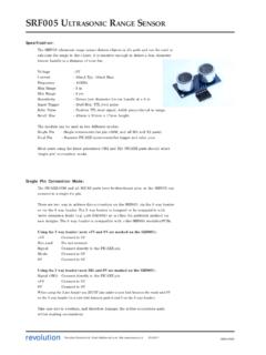
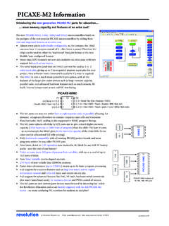
9 Click the PICAXE >Program menu to download the program to the the download the output LED should flash on and off very ! You have now programmed a microcontroller using the PICAXE system! section 1 GETTING STARTED revolution(c) Revolution Education : rights 10 a glance - specifications:Power or 5V DC is recommended. Do not use 6V, or 9V battery packs, thesecould permanently damage the chip. For trouble-shooting use 3xAA cells 28X2/40X2 parts were also previously available in special low power ( ) variants called the 28X2-3V and 40X2-3V. Note that or 5V willpermanently damage these special low power :Each output can sink or source 20mA. This is enough to light an LED but willnot, for instance, drive a motor. Total maximum current per chip is :An input should be above ( x power supply voltage) to be high, below ( xpower supply voltage) to be low. It is recommended, but not essential, to tieunused inputs low via a 10k :The ADC range is the power supply voltage range.
10 The maximum recommendedinput impedance is 20k. Unconnected ADC will float giving varying falsereadings. However touch sensor pins must float (no pullup/pulldown).Serial download pin:The serial download pin must never be left floating. This will give unreliableoperation. Always use the 10k/22k resistors as shown below, even if the chip wasprogrammed on a different pin:The reset pin (if present) must never be left floating. This will give unreliableoperation. Always tie high (ie to the positive supply) via a 4k7 or 10k a glance - download circuit: ! ! " section 1 GETTING STARTED revolution(c) Revolution Education : rights 10 a glance - pinout diagrams (older parts):# $# %# &# ' ( ") *# # ' ( ") +# ' ( ") # $ ' # $ ' ( ' % ' # % ' ( ' & ' # & ' ' # ' ' ,- ., ' * ' * ' * ' * ' / / # ) ' # ' ") ' # ' ( ") ' ") ' # ' ' ' # ' &%$01 0 $ % & 1 0 $ % &# $# %# &# # # # # $ ' % ' & $ ' # $ ' ( % ' # % ' ( & ' # & ' ' # ' '.)