Transcription of PCB scope User Manual - Picaxe
1 PCB scope user Manual Version December, 2013 1 Introduction The PCB scope is a low-cost, microcontroller based digital oscilloscope intended for hobby and educational use. It is a low cost PCB version of the DPScope SE and so shares the same circuit and software. If you are new to oscilloscopes, we recommend the following introductory application notes (created by Tektronix, one of the major oscilloscope manufacturers for the professional, high-end market) which will supply all the knowledge necessary to understand this user Manual and get the most from your PCB scope : The XYZs of Oscilloscopes The ABCs of Probes You can download both documents either from the Tektronix website ( ) or from the PCB scope website ( PCB scope Downloads).
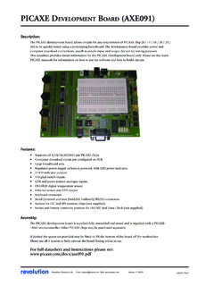
2 If after reading through the documentation you still have questions regarding the PCB scope or want to provide feedback or suggestions for improvement, do not hesitate to contact us atF 2 Software Startup After you installed the PCB scope software (see the assembly guide for details) plug in you PCB scope and wait a short time so the computer has a chance to recognize the scope . The PCB scope s power LED on the front panel should blink quickly a few times and then stay solidly on this is the sign that the scope has successfully powered up.
3 The PCB scope does not neet any special drivers since it uses the standard USB HID driver that comes with Windows. Then launch the PC software (Start PCB scope PCB scope ). After a few seconds the PCB scope program should appear on the screen. If the program cannot find and connect to the PCB scope you will get a popup (see below) that you need to confirm in order to continue. The software will still start after that, but of course you will not be able to run the acquisition. In this case, close the software, unplug the oscilloscope, plug it in again (you may want to try a different USB port if that does not help), and launch the software again.
4 (This problem is very unlikely to happen. More likely is that you simply haven t attached the scope to your computer). The PCB scope should always be attached to a USB port directly at the computer, or through a powered USB hub. Unpowered USB hubs tend to have excessive supply voltage drop which needs to be compensated for (and which will reduce the scope s maximum voltage range). If in doubt you can check the actual USB supply voltage by selecting Utilities Check USB Supply. The nominal value is 5V but in reality can be as low as The minimum required screen resolution for the PCB scope software is 800x600 pixels.
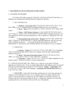
5 3 The Main Screen After startup the screen should look as shown below: The left side of the display is mostly taken up by the waveform display. To the right and on the bottom you can see that the controls are grouped in several functional blocks (we will explain each of them in more detail later): Mode: Selects the main functionality (oscilloscope, datalogger, or logic analyzer). Display: Determines how the acquired data is to be displayed. Acquisition: Main control of acquisition process Position/Level: Sets the voltage offset for each channel, and the trigger threshold level.
6 Vertical: Controls the input amplification/attenuation for each of the two input channels. Horizontal: Controls the time base, sampling speed, and delay. Trigger: Defines the trigger source. On the bottom there is a status line that displays the cursor information (right now the cursors are turned off so it is empty), which you can use to make measurements on the displayed waveforms ( to determine the signal amplitude or frequency). On the top of the screen you find the menu containing three entries, File (to save the displayed waveforms in numerical format, and to save and restore the PCB scope s software settings), Utilities (measurements, DMM display, and supply voltage check), and Help (displays general info about the software).
7 4 First Acquisition After startup the software is set up in a way to maximize you chance to see something useful on the screen right away: Both scope channels are turned on, the voltage range for both is set to maximum, ground levels centered on the screen, continuous mode and trigger in Auto mode (meaning the acquisition will run without waiting for a trigger event), and so on. Attach the analog channels to some signal source, the toggling output of a microcontroller. Press the Run button (its caption will change to Stop ). You should see a waveform on the screen.
8 Since the trigger mode is Auto , most likely the waveform will not be stable but rather jump around. Now play around a bit with some of the controls. Don t be afraid! You can t break the scope no matter what settings you change. The worst that can happen is that you no longer acquire a waveform and/or see it on the screen. If you get completely stuck, simply close down the PCB scope program and start it again. Move the offset sliders and see how the waveforms follow. Now select CH1 in the trigger control menu. Move the trigger level slider so the trigger level (indicated by a green triangle on the left border of the waveform display) is somewhere in the middle of the CH1 waveform (the red waveform).
9 That waveform should now be stable (assuming you waveform is periodic). Try switching between rising and falling edge trigger. Now change the sample rate in the Horizontal control display and see how the waveform changes (it like zooming in and out on the waveform timing). In the Display control box, turn the waveforms on and of by clicking on the appropriate checkbox (you can still trigger on a waveform even when it is not displayed). Change the display style to points and/or infinite persistence. Congratulations you have just measured your first signal with the PCB scope !
10 5 General Remarks The PCB scope is a digital storage oscilloscope (refer to the XYZs of Oscilloscope mentioned in the introduction if you are unsure what that is), based on a Microchip PIC18F14K50 microcontroller. Most of the oscilloscope functionality is actually integrated in this single chip analog-to-digital converters, sample logic, trigger logic and threshold generation, memory, logic analyzer, USB interface. Only the analog frontend (input amplifier/attenuator) consists of external components. Acquisition Modes The PCB scope s acquisition engine has four different modes (again, refer to the XYZ of Oscilloscopes document for further details): Normal Mode: Acquisition is started by a trigger event (or automatically right after the previous acquisition if the trigger mode is Auto ) and samples (digitizes) the signal in real time.